
SS Jacketed Vessel for Process Heating & Cooling
SV Industries designs and fabricates stainless steel jacketed vessels for process applications requiring controlled heating, cooling or temperature maintenance. The vessel and jacket arrangement is selected according to the process duty, operating conditions, material compatibility and required thermal performance.
A jacket provides a separate utility space around the vessel shell or head, allowing steam, hot water, thermic fluid, cooling water or chilled fluid to transfer heat through the vessel wall. Jacket type, coverage, pressure and temperature are confirmed from the project design basis.
What Is an SS Jacketed Vessel?
An SS jacketed vessel consists of a stainless steel process chamber with a separate outer jacket fitted around selected areas of the vessel. The space between the process wall and the jacket forms an independent passage for a heating or cooling utility.
The process material remains inside the main vessel while the utility circulates outside the process wall. Heat is transferred through the stainless steel wall without direct contact between the utility and the product.
Jacket coverage may be provided around the shell, the bottom head, or selected vessel zones depending on the required thermal duty and equipment configuration. Agitation may also be incorporated where mixing or improved temperature distribution is required.
Process Chamber
Contains the product or process material.
Utility Jacket
Carries the heating or cooling medium separately from the process.
Thermal Transfer Surface
Transfers heat through the vessel wall between utility and process.
Jacket Types for Process Vessels
Jacket configuration is selected according to the required heating or cooling duty, utility conditions, vessel geometry and fabrication requirements. Different jacket arrangements provide different levels of coverage, utility flow behaviour and operating flexibility.
Conventional Jacket
An outer shell creates an annular utility space around the process vessel. It may cover the shell, selected vessel zones and, where required, part of the bottom head.
Dimple Jacket
A formed jacket surface is attached to the vessel wall to create multiple utility-flow passages while maintaining close support between the jacket and vessel wall.
Half-Pipe / Limpet Coil
A formed channel is welded externally to the vessel surface to provide a defined utility path. For detailed limpet-coil design and construction, link to the dedicated Limpet Coil Reactor Vessel page.
Engineering note: The final jacket type, coverage and zoning are project-specific and confirmed from the thermal and mechanical design basis.
Conventional Jacket Coverage & Arrangement
A conventional jacket forms an outer shell around selected portions of the process vessel, creating an annular space for the heating or cooling utility. Jacket coverage is selected according to the required thermal duty, vessel geometry, utility conditions and process requirements.
Depending on the application, the jacket may cover only the cylindrical shell, extend over the bottom head, or be divided into separate operating zones.
Shell Jacket
A shell jacket covers the cylindrical portion of the vessel and provides heating or cooling through the vessel sidewall. It may be suitable where the required thermal-transfer area can be provided primarily along the straight shell section.
Shell + Bottom Head Jacket
The jacket may extend from the cylindrical shell over the bottom head where additional thermal-transfer area is required or where temperature control near the lower portion of the vessel is important.
The final extent of bottom-head coverage depends on the vessel geometry, utility arrangement and project design basis.
Zoned Jacket
A conventional jacket can be divided into separate zones so that different portions of the vessel can be supplied or controlled independently.
Zoning may be considered where the process benefits from staged heating or cooling, different operating conditions along the vessel height, or controlled utility distribution.
Engineering note: Jacket coverage is not selected from surface area alone.
Utility medium, thermal duty, vessel geometry, operating pressure and temperature, utility flow path, process conditions and required temperature control all influence the final jacket arrangement.
Utility Media for Jacketed Vessels
The heating or cooling medium is selected according to the required process temperature, heating or cooling rate, available plant utilities and the thermal design of the vessel. The same jacket configuration may operate differently depending on the utility medium, flow conditions and control arrangement.
Steam Heating
Steam may be used for heating duties where suitable plant steam conditions are available. Jacket pressure, condensate removal and temperature control are considered as part of the project design.
Hot Water
Hot water can provide moderate and controllable heating where lower process temperatures or gentler temperature control are required.
Thermic Fluid
Thermic fluid may be selected for higher-temperature heating duties where indirect heating is preferred. Utility temperature, circulation rate and system design are confirmed from the process requirement.
Cooling Water
Cooling water is commonly used where the process requires heat removal and the available utility temperature is sufficient for the required cooling duty.
Chilled Water
Chilled water may be used where the required process temperature or cooling duty cannot be achieved with the available cooling-water conditions.
Glycol / Brine Cooling
Glycol-water mixtures or brine may be used for lower-temperature cooling duties where normal cooling water or chilled water is not sufficient. The fluid concentration, operating temperature and circulation conditions are selected according to the required cooling duty and utility system design.
What Determines Jacketed Vessel Heat-Transfer Performance?
Heat-transfer performance in a jacketed vessel depends on the complete process and utility system rather than on jacket pressure or vessel size alone. The required heating or cooling duty is evaluated together with the process properties, available transfer area and utility-side operating conditions.
Final thermal performance is therefore application-specific and should be based on the project design conditions.
Process Temperature Difference
The temperature difference between the process and the heating or cooling utility provides the driving force for heat transfer. This driving force changes as the batch heats or cools.
Jacket Coverage & Transfer Area
The amount and location of jacketed surface influence the available heat-transfer area. Shell-only, shell-plus-head and zoned arrangements can provide different effective coverage.
Utility Flow & Conditions
Utility inlet temperature, flow rate, pressure where applicable, flow distribution and outlet conditions affect jacket-side heat-transfer behaviour.
Process Fluid Properties
Viscosity, density, heat capacity, thermal conductivity and changes in product properties during processing influence the required heating or cooling duty.
Agitation & Product-Side Mixing
Where agitation is provided, the impeller configuration and circulation pattern can influence temperature distribution and product-side heat transfer, particularly for viscous or non-uniform processes.
Vessel Wall & Fouling Resistance
Vessel wall material and thickness, surface condition, product deposits or fouling and other thermal resistances influence the overall heat-transfer path between the utility and the process.
Engineering note: A universal heat-transfer coefficient or fixed heating/cooling time should not be assumed for every jacketed vessel.
Thermal performance should be evaluated from the actual process duty, material properties, jacket configuration, utility conditions and operating requirements.
Materials for Jacketed Vessel Construction
Material selection for a jacketed vessel depends on the process fluid, operating temperature, corrosion environment, cleaning requirements, pressure design and required surface finish. The process-contact vessel, utility jacket and external components may use the same or different materials depending on the service conditions.
The final material grade should therefore be confirmed from the actual process and mechanical design basis.
Carbon Steel / Mild Steel — IS 2062 E250 / SA-516 Gr. 70
Carbon steel may be used where the process, utility service and corrosion conditions permit. IS 2062 E250 may be considered for suitable structural or non-pressure components, while SA-516 Gr. 70 may be specified where pressure-vessel quality carbon-steel plate is required.
SS 304 — SA-240 Type 304
SS 304 is commonly used for general stainless steel process equipment where the process chemistry, cleaning media and operating conditions are compatible with the material.
SS 316 — SA-240 Type 316
SS 316 contains molybdenum and may provide improved resistance to certain corrosive environments compared with SS 304. Suitability depends on the actual process medium, concentration, temperature and service conditions.
SS 316L — SA-240 Type 316L
SS 316L is the low-carbon version of SS 316 and is commonly considered for welded process equipment where fabrication and corrosion-service requirements favour reduced carbon content.
Duplex 2205 — SA-240 UNS S32205 / S31803
Duplex 2205 may be considered for more demanding services where higher mechanical strength and improved resistance to certain forms of corrosion are required. Selection depends on the process chemistry, temperature, fabrication requirements and applicable design basis.
Higher-Alloy Stainless Steel — 904L / Project-Specific Alloy
Higher-alloy stainless steels such as 904L may be evaluated for more severe corrosive environments where conventional austenitic stainless steels are not suitable. Final material selection should be based on the actual chemical composition, concentration, temperature and fabrication requirements.
Engineering note: A higher alloy grade is not automatically the better material for every jacketed vessel. Process chemistry, concentration, contaminants, temperature, cleaning media, pressure, welding requirements and corrosion considerations should be reviewed before finalizing the material.
Process-contact and jacket materials may be different. For example, a stainless steel process-contact vessel may use a carbon-steel jacket where the project design and utility service permit.
Design Basis for a Jacketed Vessel
A jacketed vessel is designed from both the process-side requirements and the jacket-side utility conditions. These two pressure and temperature systems are evaluated separately and then considered together as part of the vessel construction and thermal design.
Final dimensions, material thicknesses, jacket arrangement and inspection requirements are confirmed from the approved project design basis rather than from a fixed standard range.
Process Capacity & Vessel Geometry
Required working volume, total volume, vessel diameter, straight-side height, head type and operating liquid level influence the final vessel configuration.
Process-Side Pressure & Temperature
Operating and design pressure and temperature for the product side are established from the process requirements and applicable engineering basis.
Jacket-Side Pressure & Temperature
The heating or cooling circuit has its own utility pressure and temperature conditions. Jacket design conditions are therefore specified separately from the process vessel conditions.
Heating / Cooling Duty
Required heating or cooling duty, process temperature range, utility medium, available utility conditions and required batch time are reviewed when determining jacket coverage and thermal design requirements.
Material & Corrosion Requirements
Process chemistry, utility service, temperature, corrosion conditions and fabrication requirements influence the selection of vessel and jacket materials.
Agitation Requirements
Where mixing is required, product properties, viscosity, solids, process objective and operating liquid level are considered when selecting the agitator and integrating it with the vessel.
Nozzles, Openings & Access
Process inlet and outlet connections, utility connections, instrumentation, venting, drain points, manway and maintenance-access requirements are established from the process and operating needs.
Inspection & Testing Scope
Material verification, dimensional inspection, pressure or leak testing and any additional examination are defined according to the approved project specification and applicable engineering requirements.
Engineering note: Process-side and jacket-side design conditions should not be assumed to be the same. Each side may have different pressure, temperature, material and testing requirements, and their interaction is considered during the final mechanical design.
Agitation for Temperature Uniformity
A jacket transfers heat through the vessel wall, but temperature distribution within the process also depends on product-side circulation. Where required, an agitator can improve bulk mixing, reduce temperature variation within the vessel and support more consistent heating or cooling.
Agitator selection depends on the actual process duty rather than on the jacketed vessel alone.
Product Circulation
The required circulation pattern depends on the process objective, liquid level and product behaviour. Adequate movement of material helps distribute heat transferred through the jacketed surface.
Viscosity & Process Properties
Viscosity, density, solids content and changes in product properties during heating or cooling influence the required mixing approach.
Impeller & Stage Selection
Impeller type, diameter, speed and number of stages are selected according to the required mixing duty and vessel geometry. Different applications may require different impeller configurations.
Mechanical Integration
Agitator mounting, shaft arrangement, sealing, clearances and internal components are coordinated with the vessel design so the mixing system and jacketed vessel operate as an integrated assembly.
Process and Jacket Connections
A jacketed vessel requires separate connections for the process side and the heating or cooling circuit. Connection type, size, orientation and location are selected according to the process flow, utility arrangement, instrumentation and maintenance requirements.
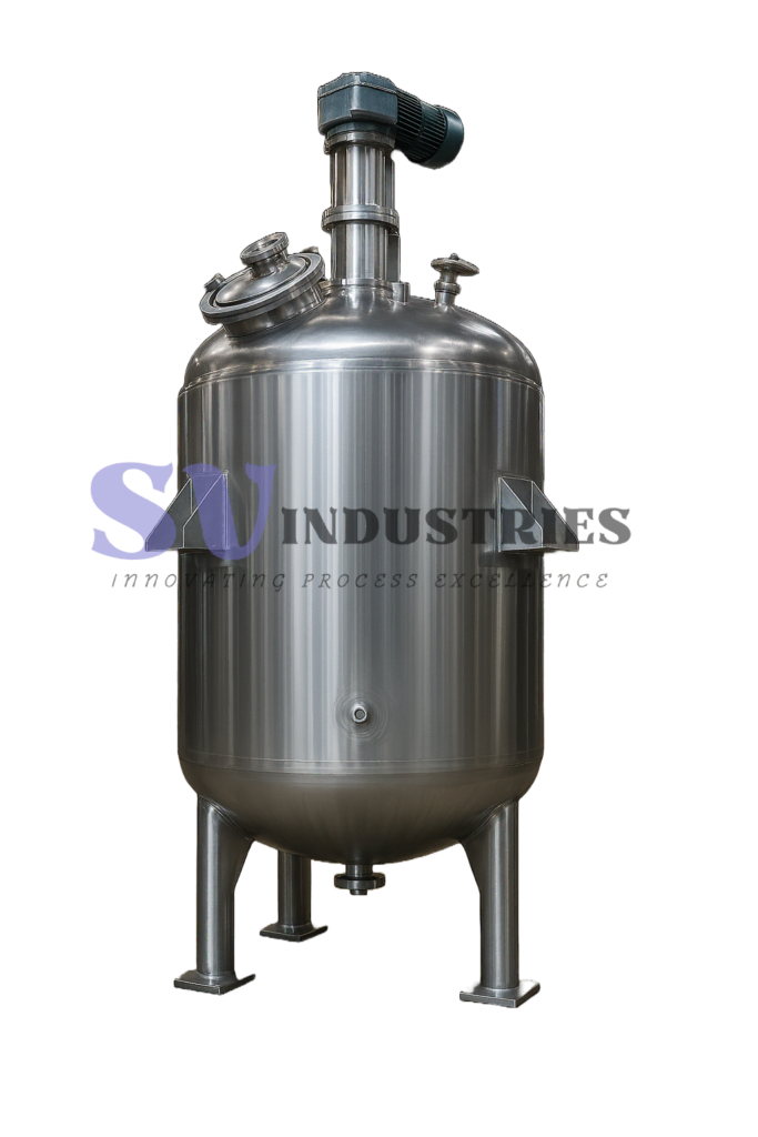
Process Inlet & Outlet
Product inlet and outlet connections are positioned according to the process sequence, vessel geometry and required drainage or transfer arrangement.
Jacket Inlet & Outlet
The utility jacket requires dedicated inlet and outlet connections to establish the required heating or cooling flow path. Their location depends on the jacket configuration, utility medium and circulation arrangement.
Vent & Drain Connections
Process and utility spaces may require venting and drainage provisions depending on the operating and maintenance requirements.
Instrument Connections
Connections may be provided for temperature, pressure, level or other instrumentation required by the process and control system.
Manway / Access Opening
Where required, a manway or other access opening is provided for inspection, cleaning and maintenance. Final size and location depend on vessel geometry and project requirements.
Cleaning / CIP Connections
Where cleaning-in-place or dedicated cleaning arrangements are required, suitable spray devices and cleaning connections may be integrated into the vessel design.
Jacketed Vessel Construction & Fabrication Details
Jacketed vessel construction is coordinated from the approved process, mechanical and utility requirements for the project. Vessel geometry, jacket configuration, openings, attachments, agitator integration and finishing requirements are incorporated into the final fabrication scope.
Final construction and inspection requirements depend on the specified materials, design conditions and project documentation.
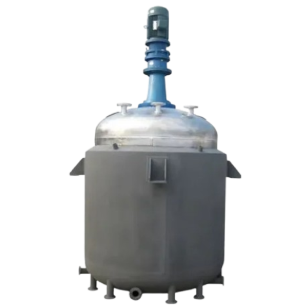
Agitator & Internal Integration
Where agitation or vessel internals are included, mounting locations, shaft entry, clearances and supporting features are coordinated with the vessel fabrication.
Surface Finish & External Construction
Surface finish, weld treatment, cleaning, insulation, cladding and other external construction details are specified according to the process service and project requirements.
Vessel & Jacket Construction
The process vessel and jacket are fabricated according to the selected geometry, material specification and design conditions. Jacket configuration and coverage are coordinated with the required heating or cooling arrangement.
Welded Attachments & Openings
Nozzles, utility connections, manways, supports and other welded attachments are positioned and fabricated according to the approved equipment arrangement and project requirements.
Inspection & Testing for Jacketed Vessels
Inspection and testing requirements are defined according to the vessel design conditions, jacket configuration, materials and approved project specification. The process vessel and utility jacket may require separate checks because their operating conditions and testing requirements can differ.
Material & Fabrication Verification
Material identification, fabrication details and project requirements are reviewed as applicable during the vessel manufacturing process.
Dimensional & Visual Inspection
Vessel dimensions, nozzle orientation, openings, supports and visible fabrication details are checked against the approved construction requirements.
Pressure / Leak Testing
Hydrostatic, pneumatic or other specified pressure or leak testing is carried out where required by the project design basis and applicable engineering requirements.
Additional Examination
Non-destructive examination or other project-specific inspection methods may be included where specified by the approved inspection scope.
Typical Jacketed Vessel Design Details
A jacketed vessel is configured from the process, thermal and mechanical requirements of the application. The final arrangement can vary in vessel geometry, jacket coverage, agitator mounting, openings, supports and utility connections according to the approved project design basis.
A technical drawing is normally prepared to define the principal equipment dimensions, connection locations and construction arrangement before fabrication.

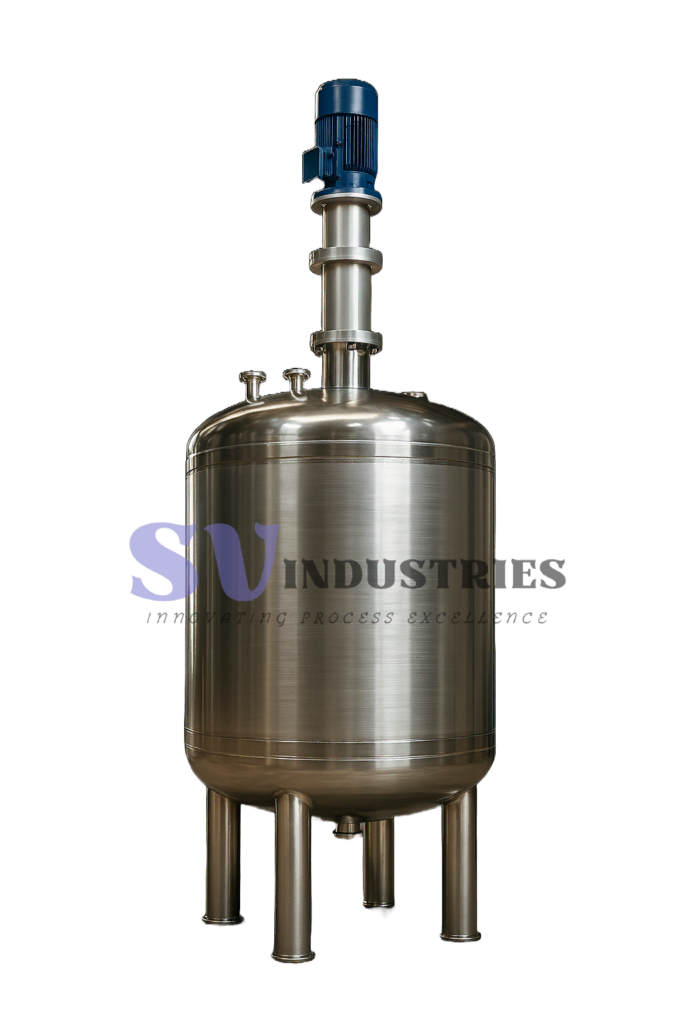
Vessel Geometry
Diameter, straight-side height, head configuration and overall arrangement are established from the required capacity and process conditions.
Jacket Coverage
The drawing identifies the selected jacketed area, such as shell-only, shell-plus-head or project-specific zones.
Process & Utility Connections
Process nozzles, jacket inlet/outlet connections, vents, drains and instrument connections are positioned according to the operating arrangement.
Agitator Integration
Where agitation is included, mounting, shaft entry and internal clearances are coordinated with the vessel layout.
Supports & Access
Legs, lugs, manways and other access or support features are incorporated according to the equipment arrangement and project requirements.
Typical Applications of Jacketed Vessels
Jacketed vessels are used where a process requires controlled heating, cooling or temperature maintenance together with product containment and, where required, agitation. The final vessel configuration depends on the product properties, thermal duty, operating conditions and required process sequence.
Heating & Temperature Maintenance
For processes that require controlled heating or maintenance of a specified operating temperature during holding, blending or processing.
Batch Cooling
For applications where heat must be removed from the product after heating, reaction, mixing or another process step.
Blending with Thermal Control
For liquid or slurry blending duties where mixing and simultaneous heating or cooling are required.
Dissolution & Preparation
For preparation processes involving dissolution, dilution or ingredient addition where controlled temperature can influence process performance.
Viscous Product Processing
For products whose viscosity or flow behaviour changes with temperature and where both thermal control and suitable agitation may be required.
Intermediate Process Holding
For temporary holding or conditioning of process material where the required temperature must be maintained before the next production stage.
Actual suitability depends on the process material, temperature range, utility system, mixing requirement and project design conditions.
Information Required for Jacketed Vessel Selection
A clear process and utility design basis helps define the vessel configuration, jacket arrangement, material selection and agitation requirements more accurately. The following information is useful when preparing a technical enquiry for a jacketed vessel.
Required Capacity
Working volume, total volume or batch quantity.
Process Material
Product name, composition, concentration and any known corrosive, abrasive or fouling characteristics.
Operating Temperature
Normal operating temperature, starting temperature and required final temperature, where applicable.
Heating / Cooling Duty
Whether the vessel requires heating, cooling, temperature maintenance or a combination of these duties.
Available Utility
Steam, hot water, thermic fluid, cooling water, chilled water, glycol/brine or another available plant utility.
Pressure Conditions
Process-side and jacket-side operating or design pressure requirements, where known.
Mixing Requirement
Viscosity, density, solids content, operating liquid level and the required mixing objective where agitation is needed.
Material & Construction Requirements
Preferred product-contact material, jacket material, surface finish, insulation, cladding, nozzle/access requirements and any project-specific inspection scope.
Have a process datasheet or equipment requirement?
Send the available process and utility information for technical review.
SS Jacketed Vessel FAQs
What is an SS jacketed vessel?
An SS jacketed vessel is a stainless steel process vessel with a separate outer jacket through which a heating or cooling utility circulates. Heat is transferred through the vessel wall without direct contact between the utility and the process material.
Which heating or cooling media can be used in a jacketed vessel?
Depending on the process and available plant utilities, the jacket may use steam, hot water, thermic fluid, cooling water, chilled water or glycol/brine. Final utility selection depends on the required temperature range, thermal duty and system conditions.
Are process-side and jacket-side pressures the same?
Not necessarily. The process vessel and utility jacket are separate pressure and temperature systems and may have different design conditions. Each side is evaluated according to its own operating requirements.
What is the difference between a conventional jacket and a limpet coil?
A conventional jacket creates an annular utility space around part of the vessel, while a limpet or half-pipe coil provides a defined external utility flow path welded to the vessel surface. Selection depends on the thermal and mechanical requirements of the application.
Which material is suitable for a jacketed vessel?
Material selection depends on the process chemistry, temperature, corrosion conditions, cleaning requirements and mechanical design. Depending on the application, materials may include carbon steel, SS 304, SS 316, SS 316L, Duplex 2205 or other project-specific alloys.
Does every jacketed vessel require an agitator?
No. Agitation is selected only where the process requires mixing, circulation, suspension, blending or improved temperature distribution. The agitator type and configuration are determined from the actual mixing duty and product properties.
What information is required for a jacketed vessel quotation?
Useful information includes required capacity, process material, operating temperature, heating or cooling duty, available utility, process- and jacket-side pressure conditions, material requirements and mixing requirements where applicable.
Related Jacketed Vessel Resources
Continue with related resources for jacket configuration, mixing, vessel sizing and thermal-system selection.
01
Limpet Coil Reactor Vessel
Reactor vessels with external limpet or half-pipe coil arrangements for process temperature control, with agitator configuration coordinated with the vessel design.
02
Industrial Agitator
Agitator systems configured for blending, suspension, heat transfer and other process mixing duties.
03
Limpet Coil Length Calculator
Calculate approximate limpet-coil length for vessel shells and supported dished-end geometries.
04
Industrial Chemical Reactor
Industrial chemical reactor configurations for project-specific reaction, mixing and thermal-processing requirements.
Discuss Your Jacketed Vessel Requirement
Share your process capacity, material, operating temperature, heating or cooling duty, available utility and mixing requirements. SV Industries can review the available process information and develop a jacketed vessel configuration according to the project design basis.