
Limpet Coil Reactor Vessel for Process Heating & Cooling
SV Industries designs and fabricates limpet coil reactor vessels with external half-pipe or formed-channel coils for process heating and cooling.
The limpet arrangement is engineered according to the vessel geometry, required coil coverage, utility conditions, process thermal duty and agitation requirements. Depending on the application, the coil may be provided over the shell only or extended over the shell and bottom head.
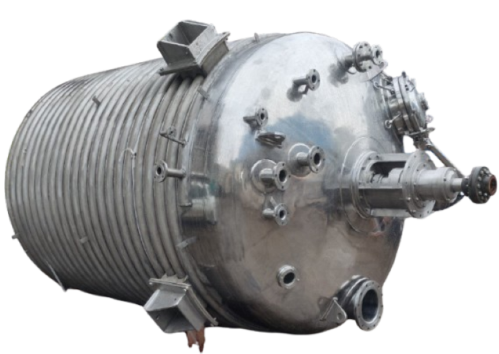
What Is a Limpet Coil Reactor Vessel?
A limpet coil reactor vessel is a process vessel in which an external half-pipe or formed-channel coil is welded to the vessel surface to provide indirect heating or cooling.
A heating or cooling utility flows through this external channel while the process material remains inside the vessel. Heat is transferred through the vessel wall, allowing the process temperature to be controlled without direct contact between the utility and the product.
The limpet coil arrangement can be engineered for different vessel geometries and thermal duties, with the required coil size, pitch, coverage and utility conditions selected according to the project design basis.
External Thermal Channel
The limpet coil forms a defined utility flow path on the outside of the vessel.
Indirect Heating or Cooling
Steam, hot water, thermic fluid, cooling water or chilled fluid may be used, depending on the required heating or cooling duty and available utility conditions.
Project-Specific Configuration
Coil coverage, routing and design conditions are selected according to the vessel geometry, process requirements and utility system.
How a Limpet / Half-Pipe Coil Works
A limpet or half-pipe coil creates a separate utility flow path on the outside of the reactor vessel. The heating or cooling medium circulates through this external channel while the process material remains inside the vessel.
Heat is transferred through the vessel wall between the process and the utility, with the direction of heat flow depending on whether the reactor is being heated or cooled.
Utility Enters the Coil
The selected heating or cooling medium enters the limpet coil through a dedicated utility connection.
Utility Flows Through the External Channel
The utility follows the welded half-pipe or formed-channel path over the selected vessel surface. The routing and coverage are determined by the vessel geometry and project design basis.
Heat Transfers Through the Vessel Wall
During heating, thermal energy passes from the utility through the vessel wall to the process. During cooling, heat is removed from the process through the vessel wall into the cooling medium.
Utility Leaves Through the Outlet
After passing through the specified coil path, the utility leaves through the outlet and returns to the associated heating or cooling system. Final flow conditions and connection details are defined from the project requirements.
Limpet Coil vs Conventional Jacket
Both limpet coils and conventional jackets provide indirect heating or cooling through the vessel wall, but their construction and utility flow paths are different.
A conventional jacket creates an annular utility space around the vessel, while a limpet or half-pipe coil forms a defined external flow channel welded to the vessel surface. The appropriate arrangement depends on the process duty, vessel geometry, utility conditions and project design requirements.
| Design Aspect | Limpet / Half-Pipe Coil | Conventional Jacket |
|---|---|---|
| Utility Space | Defined external channel formed on the vessel surface | Annular utility space created by an outer jacket around the vessel |
| Construction | Half-pipe or formed channel welded externally to the vessel wall | Separate outer jacket shell fitted around the vessel |
| Utility Flow Path | Utility follows a defined coil or channel path | Utility flows through the jacketed space surrounding the vessel wall |
| Coverage | Routing and coverage are selected for the required vessel area | Jacket coverage is selected according to vessel geometry and process requirements |
| Shell & Head Arrangement | May be provided over the shell and, where required, the bottom head | May be configured for shell-only or shell-and-head coverage depending on the design |
| Key Design Variables | Coil size, pitch, routing, coverage and utility conditions | Jacket geometry, coverage, utility conditions and flow arrangement |
| Selection Basis | The appropriate arrangement is selected according to the thermal duty, vessel geometry, process conditions, utility system and mechanical design requirements. | |
Neither arrangement is universally better; the appropriate configuration depends on the project-specific thermal, hydraulic and mechanical design requirements.
Looking for a conventional jacketed configuration?
View our SS Jacketed Vessel design options.
Limpet Coil Configurations
The limpet coil arrangement can be configured over different areas of the reactor vessel according to the required thermal duty, vessel geometry and process conditions. Coil coverage is therefore established from the project design basis rather than from a fixed standard arrangement.
Shell-Only Limpet Coil
In a shell-only arrangement, the limpet or half-pipe channel is provided over the cylindrical shell section of the vessel.
This configuration provides a defined heating or cooling surface along the selected shell height. The required coil coverage, pitch, channel size and utility connections are determined from the thermal and mechanical design requirements.
Typical design considerations
– Required heat-transfer area on the shell
– Normal operating liquid level
– Coil start and end locations
– Utility inlet and outlet arrangement
– Coil pitch and routing
– Nozzle, support and insulation clearances
Shell + Bottom-Head Limpet Coil
Where additional thermal-transfer area or bottom-region temperature control is required, the limpet arrangement may extend from the cylindrical shell onto the bottom head.
The coil path over the bottom head must follow the selected head geometry and be coordinated with the vessel outlet, supports, nozzles and other external attachments.
Typical design considerations
– Required shell and bottom-head coverage
– Bottom-head geometry
– Process liquid contact with the head
– Coil routing over curved surfaces
– Bottom outlet and nozzle clearances
– Utility flow path and drainage requirements
Configuration is project-specific.
The final coil coverage is selected from the required thermal duty, vessel geometry, process conditions, available utility system and mechanical design requirements.
Utility Media for Limpet Coil Heating & Cooling
The utility medium is selected according to the required heating or cooling duty, operating temperature range, available plant utilities and project design conditions. The limpet coil and utility connections are then engineered for the selected service.
Steam
Hot Water
Thermic Fluid
Cooling Water
Chilled Fluid
What Determines Limpet Coil Thermal Performance?
Temperature Difference
The temperature difference between the process and the heating or cooling utility provides the driving force for heat transfer. This difference changes during the batch as the process temperature changes.
Coil Coverage & Heat-Transfer Area
The vessel area covered by the limpet coil influences the available surface for heat transfer. Required coverage is established from the thermal duty and vessel geometry.
Utility Conditions & Flow
Utility inlet temperature, pressure where applicable, flow rate and circulation conditions influence the heat available for heating or the heat that can be removed during cooling.
Process Fluid Properties
Process mass, specific heat, viscosity, thermal conductivity and phase behaviour can significantly affect heating or cooling requirements.
Agitation & Process Circulation
Agitation can improve process-side circulation and help reduce temperature gradients inside the vessel. The actual effect depends on the selected impeller, speed, liquid level and process properties.
Wall, Fouling & Insulation Effects
Vessel-wall resistance, product-side or utility-side fouling and heat loss to the surroundings can affect overall thermal performance. Insulation may be provided where required by the operating conditions.
Thermal performance is application-specific.
Heating or cooling time should be calculated from the actual process load, utility conditions, available heat-transfer area and relevant thermal resistances.
Process-Side & Limpet-Side Design Conditions
A limpet coil reactor vessel has two distinct design environments: the process contained inside the vessel and the heating or cooling utility flowing through the external limpet channel.
The operating and design conditions for each side should therefore be established separately before the vessel, limpet coil and utility connections are finalized.
Process Side
The process-side design basis defines the conditions inside the reactor vessel.
Key inputs may include:
- Process fluid or product
- Working and maximum liquid level
- Operating pressure or vacuum
- Design pressure
- Operating and design temperature
- Process fluid properties
- Agitation requirements
- Material compatibility
- Corrosion allowance, where applicable
- Cleaning or process-specific requirements
Limpet / Utility Side Design Basis
The limpet-side design basis defines the conditions inside the external half-pipe or formed channel.
Key inputs may include:
- Heating or cooling utility
- Utility operating pressure
- Limpet-side design pressure
- Utility inlet temperature
- Limpet-side design temperature
- Required utility flow rate
- Coil size and routing
- Coil pitch and coverage
- Utility inlet and outlet arrangement
- Venting and drainage requirements, where applicable
Engineering Note
Process-side and limpet-side design pressures and temperatures are not assumed to be the same. Each side is evaluated from its own service conditions, and the final mechanical design is coordinated with the approved project design basis.
Materials of Construction for Limpet Coil Reactors
Material selection for a limpet coil reactor vessel depends on the process fluid, operating and design temperatures, corrosion conditions, cleaning requirements, utility service and fabrication requirements.
The process-wetted vessel material and the external limpet-coil arrangement are therefore selected from the approved project design basis rather than from a universal material rule.
Carbon Steel
Carbon steel may be considered where it is compatible with the process and utility service and where the project corrosion and fabrication requirements permit its use.
- Process compatibility
- Corrosion allowance, where applicable
- Design temperature
- Utility service
- Required surface protection or lining, where specified
Stainless Steel 304
SS304 may be considered for applications where its corrosion resistance, cleanability and fabrication characteristics are suitable for the specified process conditions.
- Process chemistry
- Operating temperature
- Cleaning requirements
- Surface-finish requirements
- Utility and external environmental conditions
Stainless Steel 316 / 316L
SS316 or SS316L may be considered where the process environment requires a different corrosion-resistance or fabrication basis than SS304, subject to application-specific review.
- Process chemistry and concentration
- Operating and design temperature
- Contaminants or chlorides, where relevant
- Welding and fabrication requirements
- Cleaning and surface-finish requirements
Higher-Alloy / Project-Specific Materials
Higher-alloy materials may be evaluated where the process environment cannot be adequately addressed by the standard carbon-steel or stainless-steel options.
Final selection is based on the actual service conditions, applicable material specifications and project engineering review.
Agitation Integration in Limpet Coil Reactors
In a limpet coil reactor, agitation and thermal control should be considered together. The external coil provides heating or cooling through the vessel wall, while the agitator promotes circulation of the process fluid inside the vessel.
Effective internal circulation can help reduce temperature gradients and improve contact between the process fluid and the heat-transfer surface. The actual agitator configuration is selected according to the process duty, fluid properties, vessel geometry and operating conditions.
Process Circulation
The agitator promotes circulation of the process fluid through the vessel, helping renew fluid adjacent to the heated or cooled vessel wall.
Impeller Selection
Impeller type is selected according to viscosity, solids content, gas involvement, blending duty and required flow pattern rather than from vessel volume alone.
Speed & Power
Agitator speed and power depend on the selected impeller, vessel geometry, process properties and required mixing duty. Fixed motor-power values should not be applied solely from reactor capacity.
Mechanical Coordination
Agitator shaft, impeller position, internal clearances, nozzles, supports and limpet-coil arrangement should be coordinated as part of the overall reactor design.
Need to review the mixing system separately?
View our Industrial Agitator Systems for impeller, shaft, drive and process-mixing options.
Process & Utility Connections
Process nozzles, utility connections and instrumentation points are coordinated with the vessel geometry and limpet-coil routing so that the required process functions and external clearances can be maintained.
Final connection size, rating, orientation and location are established from the approved process, mechanical and utility requirements.
Process Nozzles
Limpet Coil Inlet & Outlet
Venting & Drainage
Instrumentation Connections
External Clearance & Insulation Coordination
Limpet Coil Construction & Fabrication
Limpet coil fabrication requires the external channel to be formed, positioned and welded to the vessel surface in accordance with the approved vessel geometry and coil layout.
Coil routing, weld accessibility and nearby nozzles, supports and other attachments are coordinated during fabrication so that the completed arrangement matches the project design basis.
Channel Forming
The half-pipe or formed channel is prepared to suit the selected vessel geometry and required coil path. Curved portions are formed according to the applicable shell or head profile.
Coil Fit-Up & Routing
The formed channel is positioned over the specified vessel area with the required routing, pitch and clearances before final welding.
Welding to the Vessel Surface
The limpet channel is welded to the vessel surface using the approved fabrication and welding requirements for the project. Weld details depend on the selected materials, geometry and mechanical design basis.
Coordination with Attachments
Coil routing is coordinated with nozzles, supports, lifting points, insulation provisions and other external attachments to avoid interference and maintain required access.
Dimensional & Fabrication Checks
During fabrication, the coil path, connection locations, clearances and overall arrangement are checked against the approved drawings and project requirements.
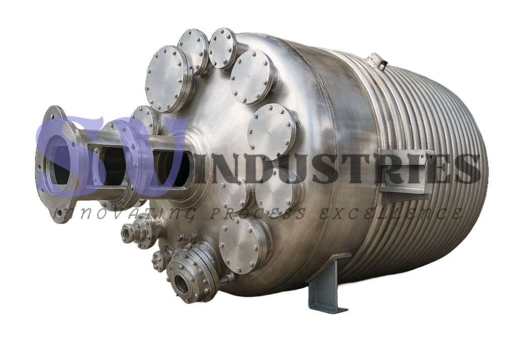
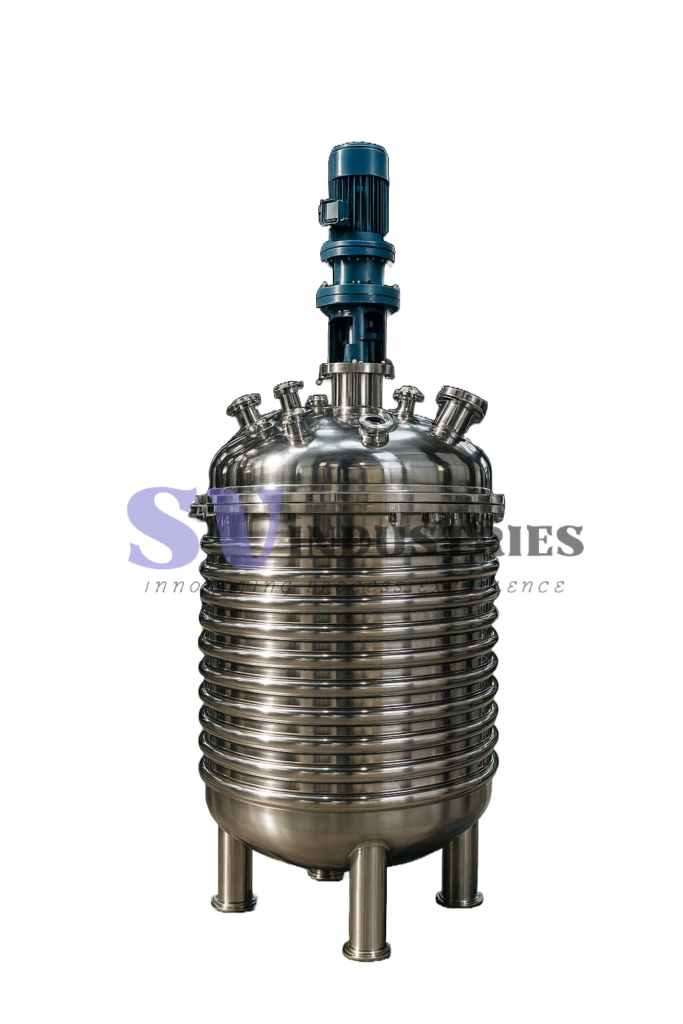
Fabrication details are project-specific.
Final channel geometry, weld details, inspection requirements and fabrication sequence are established from the approved design documents and applicable project requirements.
Inspection & Testing of Limpet Coil Reactor Vessels
Inspection and testing requirements are established from the vessel design, limpet-coil service conditions, materials of construction and approved project specifications.
The process vessel and external limpet circuit are inspected and tested separately where applicable, with the required examination and test scope defined for the individual project.
Visual & Dimensional Inspection
Weld Examination
Limpet Circuit Leak / Pressure Testing
Vessel Pressure / Leak Testing
Final Inspection & Documentation
Typical Limpet Coil Reactor Configuration
A limpet coil reactor combines the process vessel, external half-pipe heating or cooling channel, agitation system, process connections and vessel supports into one coordinated equipment arrangement.
The illustration below identifies the principal components of a typical limpet coil reactor. The final vessel geometry, coil coverage, nozzle arrangement, agitator configuration and support details are developed from the approved project design basis.
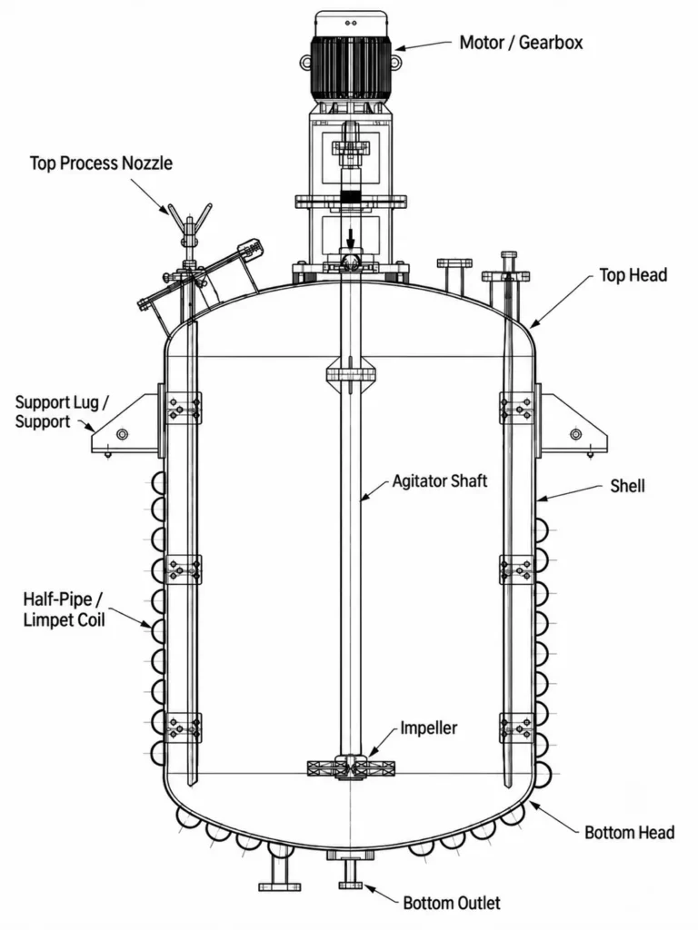
Typical sectional configuration of an agitated limpet coil reactor vessel.
Illustrative configuration only.
Actual vessel geometry, limpet-coil coverage, nozzle locations, agitator arrangement and support details are finalized according to the project-specific process, thermal and mechanical design requirements.
Typical Applications for Limpet Coil Reactor Vessels
Limpet coil reactor vessels are used where the process requires controlled heating or cooling together with agitation inside the vessel.
The suitability of a limpet-coil arrangement depends on the process chemistry, thermal duty, operating conditions, required mixing duty and material-selection basis.
Chemical Reactions
For batch or semi-batch processes requiring agitation with controlled heating or cooling during reaction.
Dissolution & Blending
For processes where solids or liquids are blended or dissolved while the batch temperature is controlled through the vessel wall.
Resin & Polymer Processing
For temperature-controlled mixing duties involving resins, intermediates or polymer-related process materials, subject to the required viscosity and thermal design.
Specialty Chemical Processing
For customized batch processes where process temperature, agitation and utility conditions must be coordinated around a defined recipe or operating sequence.
Heating / Cooling of Process Liquids
For applications where a process liquid requires indirect heating, cooling or temperature holding while remaining contained inside the vessel.
Temperature-Controlled Mixing
For processes where agitation and external thermal control are required together to support product circulation and the target operating temperature.
Application suitability is process-specific.
Final reactor configuration should be selected from the actual process duty, fluid properties, temperature profile, utility availability, material compatibility and agitation requirements.
Estimate Limpet Coil Length for Shell & Dished-End Coverage
During preliminary layout, the required limpet coil length depends on the vessel diameter, coil size, pitch, selected coverage and the geometry of the vessel surfaces being covered.
SV Industries’ Limpet Coil Length Calculator provides an engineering estimate for coil routing over the cylindrical shell and supported dished-end geometries. It is intended for preliminary planning and should be verified against the final vessel geometry, coil arrangement and approved fabrication design.

Limpet Coil Length Calculator with shell and dished-end geometry visualization.
Information Required for a Limpet Coil Reactor Enquiry
A useful technical proposal starts with the process and utility design basis. Providing the key operating, thermal and mechanical inputs helps define the vessel configuration, limpet-coil arrangement, agitation requirement and material selection more accurately.
Where some information is not yet finalized, it can be marked as Unknown / To Be Confirmed during the initial enquiry.
Process Fluid & Service
Provide the process material, product or chemical service, including concentration or composition where relevant.
Working & Total Volume
Specify the required working volume and, where available, the intended total vessel volume or operating liquid level.
Process Pressure & Temperature
Provide normal operating pressure or vacuum, operating temperature and the required design pressure and design temperature where already defined.
Heating / Cooling Duty
Describe whether the reactor requires heating, cooling or both, together with the initial temperature, target temperature and required batch or heat-up / cool-down time if known.
Available Utility
Specify the available heating or cooling medium, such as steam, hot water, thermic fluid, cooling water or chilled fluid, together with available utility pressure, temperature and flow information where known.
Material of Construction
State the preferred vessel material, if already specified, together with any known corrosion, cleaning or surface-finish requirements.
Agitation Requirement
Provide the mixing duty, viscosity range, solids content, gas involvement or other process information that may influence impeller and agitator selection.
Vessel & Project Requirements
Include any known vessel orientation, head type, nozzle requirements, support preference, insulation requirement, applicable code or project-specific fabrication / inspection requirements.
Incomplete information is acceptable at the enquiry stage.
Unknown items can be reviewed during technical discussion, but final equipment design and quotation depend on the approved process, utility and mechanical design basis.
Frequently Asked Questions (FAQs) about Limpet Coil Reactor Vessel
What is a Limpet Coil Reactor Vessel?
A limpet coil reactor vessel is a process vessel with an external half-pipe or formed-channel coil welded to the vessel surface. A heating or cooling utility flows through this external channel while the process material remains inside the vessel, allowing indirect heat transfer through the vessel wall.
What is the difference between a limpet coil and a conventional jacket?
A limpet or half-pipe coil forms a defined external utility flow path welded to the vessel surface. A conventional jacket creates a separate annular utility space around the vessel. The appropriate arrangement depends on the thermal duty, vessel geometry, utility conditions and mechanical design requirements.
Can a limpet coil reactor be used for both heating and cooling?
Yes. Depending on the project requirements and available utilities, a limpet coil may be used with heating or cooling media such as steam, hot water, thermic fluid, cooling water or chilled fluid. Final utility conditions are established from the required thermal duty and design basis.
Can the limpet coil cover both the shell and bottom head?
Yes, where required by the thermal design. A limpet coil may be arranged over the cylindrical shell only or extended over the shell and bottom head. The final coverage and routing depend on the vessel geometry, required heat-transfer area, process conditions and fabrication clearances.
How are limpet coil size, pitch and coverage selected?
Coil size, pitch, routing and coverage are not selected from vessel capacity alone. They are established from the required thermal duty, available heat-transfer area, utility conditions, vessel geometry, hydraulic requirements and mechanical design considerations.
Does agitation affect heating or cooling performance?
Agitation can improve process-side circulation and help reduce temperature gradients inside the vessel. Its actual effect depends on the impeller type, speed, vessel geometry, liquid level and process-fluid properties, so agitator selection should be coordinated with the thermal design.
Which materials can be used for a limpet coil reactor vessel?
Common project materials may include carbon steel, SS304, SS316 and SS316L, with other materials considered where required. Final material selection depends on the process chemistry, concentration, temperature, impurities, cleaning requirements, corrosion conditions and fabrication basis.
How is limpet coil length estimated?
Limpet coil length depends on factors including vessel diameter, selected coil size, surface pitch, shell coverage and the geometry of any dished-end area being covered. The Limpet Coil Length Calculator can be used for preliminary shell and supported dished-end coil-layout estimates.
What information is required for a limpet coil reactor quotation?
Useful enquiry information includes the process fluid, working volume, operating and design pressure and temperature, heating or cooling duty, available utility, preferred material, agitation requirements and known vessel or project specifications. Information that is not yet finalized can be marked as Unknown / To Be Confirmed during the initial enquiry.
Related Engineering Resources
Continue with related resources for jacket configuration, mixing, vessel sizing and thermal-system selection.
01
SS Jacketed Vessel
For projects where a conventional annular jacket may be considered instead of an external half-pipe or limpet arrangement.
02
Limpet Coil Length Calculator
Calculate approximate limpet-coil length for vessel shells and supported dished-end geometries.
03
Industrial Agitator
Agitator systems configured for blending, suspension, heat transfer and other process mixing duties.
04
Vessel Volume & Level Calculator
Estimate vessel capacity or liquid volume from geometry and level for supported vessel configurations.
Discuss Your Limpet Coil Reactor Requirement
Share your process, vessel, utility and agitation requirements with SV Industries for a project-specific review of the limpet coil reactor configuration.
Where some inputs are not yet finalized, they can be discussed during the initial technical review.