Agitator Selection Guide for Chemical Process Plants — Types, Sizing & Material Choices
To choose the right agitator for chemical process plants, define your process goals, tank geometry, and desired flow pattern; then select impeller type, compatible material, and verify performance through pilot trials.
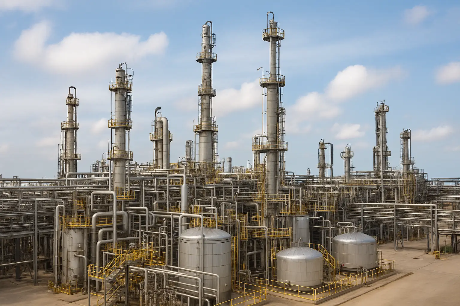
Selecting the right agitator is one of the most crucial decisions in any chemical process plant. Every reactor, mixing tank, or storage vessel behaves differently based on viscosity, specific gravity, and reaction type—so a single agitator design never fits all. A well-selected industrial agitator improves product consistency, energy efficiency, and operational reliability.
At SV Industries, our engineering team helps process plants translate their mixing goals into customized agitator solutions that match impeller geometry, motor drive configuration, and corrosion-resistant materials. From laboratory scale to full-plant reactors, we guide clients through design validation, pilot trials, and CFD-based flow checks before final production.
When it comes to agitator sizing, flow direction (axial vs radial), and impeller type, even a small mismatch can affect yield or cause unnecessary power consumption. That’s why understanding the process environment is as critical as the equipment itself. For a deeper understanding of impeller styles and flow behavior, explore our detailed Agitator overview page.
Share your tank capacity and viscosity details—our experts at SV Industries will suggest the ideal impeller and drive setup. Contact SV Industries today.
Why Agitator Selection Matters in Chemical Process Plants
Selecting the right agitator is not just an equipment choice — it determines process yield, safety, and operating cost. A mismatched impeller type or incorrect agitator sizing can lead to phase separation, poor dispersion, excessive power draw, and more frequent mechanical failures. In chemical process environments—where viscosity, specific gravity (SG) and reactive chemistries vary—these problems quickly cascade into lost production and higher lifecycle cost.
Good selection aligns three things: the mixing objective (circulation, dispersion, suspension), the vessel geometry (baffles, aspect ratio, inlet/outlet), and the fluid rheology. For example, axial flow designs with a hydrofoil impeller are often the most energy-efficient agitators for low–medium viscosity tasks, while turbine or anchor impellers handle high-viscosity or wall-scraping duties better. Beyond performance, correct material selection and sealing strategy protect against corrosion and contamination—critical in chemical plants handling aggressive chemistries.
Operational reliability also depends on installation and control: matching the motor/drive and using controls like VFD for soft starts reduces shock loads and extends life. Finally, validation—pilot trials or CFD—reduces scale-up risk and verifies real-world mixing efficiency before committing to production equipment.
Beyond process performance, proper agitator selection directly influences long-term maintainability and operational stability inside chemical plants. When the impeller geometry, shaft length, and mounting arrangement are aligned with the vessel’s actual operating conditions, the system experiences less vibration, smoother torque transmission, and reduced wear on seals and bearings. This not only increases mixer uptime but also ensures safer handling of exothermic or sensitive reactions. By choosing an agitator that complements the plant’s batch cycle, cleaning method, and CIP/SIP routines, chemical manufacturers gain better control over product quality while keeping maintenance interventions predictable and cost-effective.
| Selection Aspect | Right Choice Outcome | Wrong Choice Risk |
|---|---|---|
| Impeller Type | Uniform mixing and balanced flow pattern | Dead zones or excessive shear |
| Agitator Sizing | Energy-efficient operation and optimal torque | Motor overload or poor blending |
| Material Choice | Corrosion resistance and longer life | Frequent maintenance or contamination |
When designing an agitator for chemical process plants, consider CFD validation or a pilot trial to confirm flow pattern and mixing time before full-scale deployment.
Define process goals first — what do you need the agitator to do?
Start by listing the process goals — e.g., blend, suspend solids, disperse gas, heat/cool or control reaction — because the right agitator for chemical process plants is chosen to meet those exact objectives. Clarifying goals up front narrows down impeller types, flow pattern (axial vs radial), and material selection, and avoids costly retrofits.
The first step in any agitator selection guide is to define measurable process goals: target homogeneity, acceptable mixing time, solids suspension threshold, heat transfer requirement, and allowable shear. These goals determine whether you need axial flow for bulk circulation, radial flow for high-shear dispersion, or a combined approach with multiple impeller types.
Consider fluid properties (viscosity, density, abrasiveness) and vessel constraints (baffles, aspect ratio, ports). Early decisions influence agitator sizing, torque estimation, and whether to include a VFD for variable speed control. For critical chemistries, plan a pilot trial and CFD validation to confirm scale-up assumptions before committing to a full reactor agitator.
Use this quick decision table to map goals → agitator action:
When you define goals clearly, SV Industries can match the right industrial agitator and propose material selection and pilot testing to reduce risk. Embed internal links to learn more about specific components like the Agitator design or sizing a Reactor Vessel for mixing compatibility.
| Process Goal | Primary Action | Typical Impeller Type |
|---|---|---|
| Bulk mixing (low shear) | Axial circulation | Hydrofoil impeller |
| High-shear dispersion | Radial flow | Turbine impeller |
| Viscous blending | Wall scraping / slow turn | Anchor / Helical impeller |
Axial vs Radial Flow — Mixing Performance Comparison
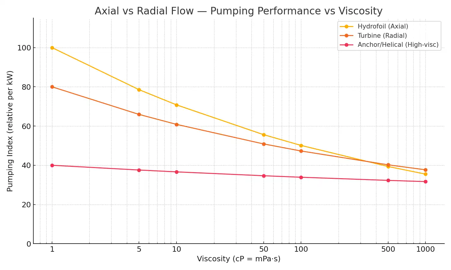
Axial and radial impellers behave very differently as viscosity (cP) rises: axial (hydrofoil) gives high pumping per kW at low-viscosity but loses effectiveness with thicker fluids, while radial (turbine) preserves shear for dispersion. Assumption: performance normalized at D/T=0.33 and RPM scaling ∝ cP⁻⁰·¹⁵ (water-like SG=1.0).
Interpretation & takeaway:
the plot shows Hydrofoil (Axial) with the highest pumping index at low viscosities (≈100 at 1 cP), declining steeply as viscosity climbs; Turbine (Radial) starts lower (~80) but falls more gradually, retaining better dispersion capability at mid-viscosities. Anchor/Helical stays low in pumping index but is comparatively stable — useful for wall-sweeping duties in high-viscous reactors. Engineering takeaway: choose hydrofoil for low-viscosity, energy-efficient circulation; choose turbine when mid-viscosity dispersion or gas dispersion is priority; for very viscous duties consider anchor/helical and pilot validation. For specific sizing and pilot trials, contact SV Industries and reference your viscosity (cP) and tank volume (L).
Tank geometry & mounting considerations
Selecting the agitator for chemical process plants starts with tank geometry and mounting — these define flow pattern, shaft access, and maintenance envelope long before you choose an impeller type. Poorly matched reactor layout causes dead zones, seal failures, and difficult agitator maintenance.
Tank shape (cylindrical vs conical), aspect ratio, and presence of baffles control whether you need axial flow (for bulk circulation) or radial flow (for dispersion). Top-mounted units suit most stirred tanks and simplify shaft seals, while side-mount or bottom-entry options are used for very large volumes, high-viscosity slurries, or when internal equipment limits top access. Consider port locations, manways, and internal obstructions when planning agitator sizing and torque estimation.
Ensure adequate impeller clearance and submergence for the expected operating level; too little clearance creates poor circulation and dead zones, while excessive submergence can increase drag and power draw. Account for baffle width, inlet momentum and filler nozzles so the impeller diameter and position actually deliver the intended flow pattern—these layout choices directly affect mixing efficiency and long-term energy use.
Design the support and drive arrangement with shaft stiffness, bearing placement and removable couplings in mind so you can perform alignments and seal replacements without major lifts. Provision for vibration monitoring, a torque meter and easy access for bearing inspection will reduce unplanned downtime and extend bearing life and seal reliability.
When planning layout, include shaft sealing strategy, bearing placement, and allowance for a VFD and coupling guard. Run a CFD validation or pilot trial for complex internals to confirm circulation and prevent dead zones.
| Mounting | Best for | Key drawback |
|---|---|---|
| Top-mounted | General-purpose tanks, easy access | Limited for very viscous fluids |
| Side-mounted | Retrofits, limited headroom | Alignment & leakage risk |
| Bottom-entry | High-viscosity, solids handling | Harder maintenance access |
Impeller types & recommended use-cases
Choosing the right impeller types is central to any agitator selection guide — the impeller defines flow pattern, shear, and energy efficiency. For agitator for chemical process plants, match the impeller family to the duty: axial flow impellers (low-shear, high circulation) for bulk blending and heat transfer, and radial flow impellers (high-shear) for dispersion and gas-liquid mixing.
- Hydrofoil impeller — excellent for axial flow, low power draw and quick bulk circulation; ideal for low-to-medium viscosity blending and energy-efficient systems. See our Hydrofoil Impeller details.
- Turbine / Rushton-style impeller — creates radial flow and high shear for dispersions, gas dispersion and solid wetting (refer to Rushton Turbine designs).
- Anchor / Helical impeller — used in high-viscosity mixing where wall-scraping and gentle folding are required.
- Paddle / Concave disc — good for suspending solids and medium-viscosity blending.
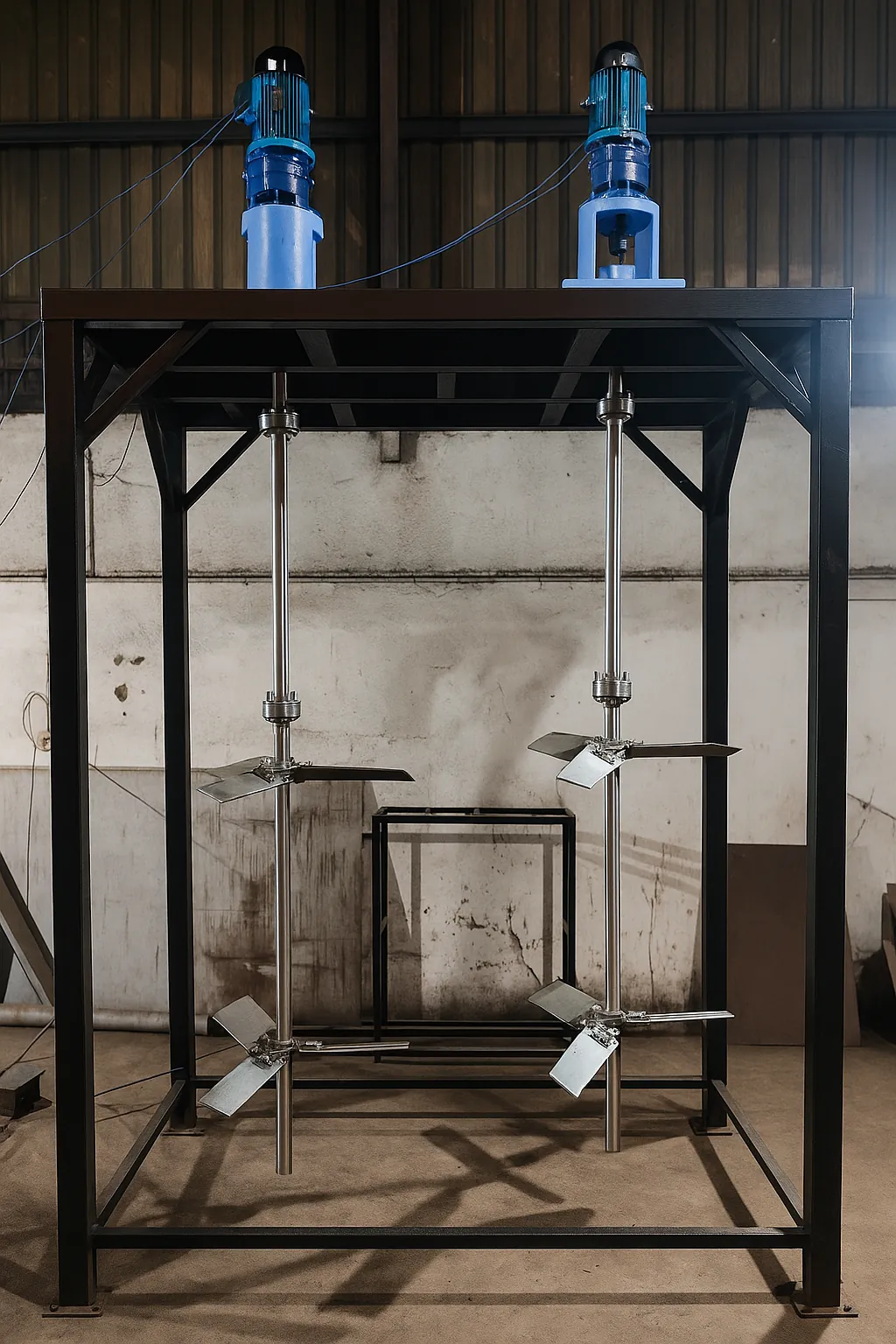
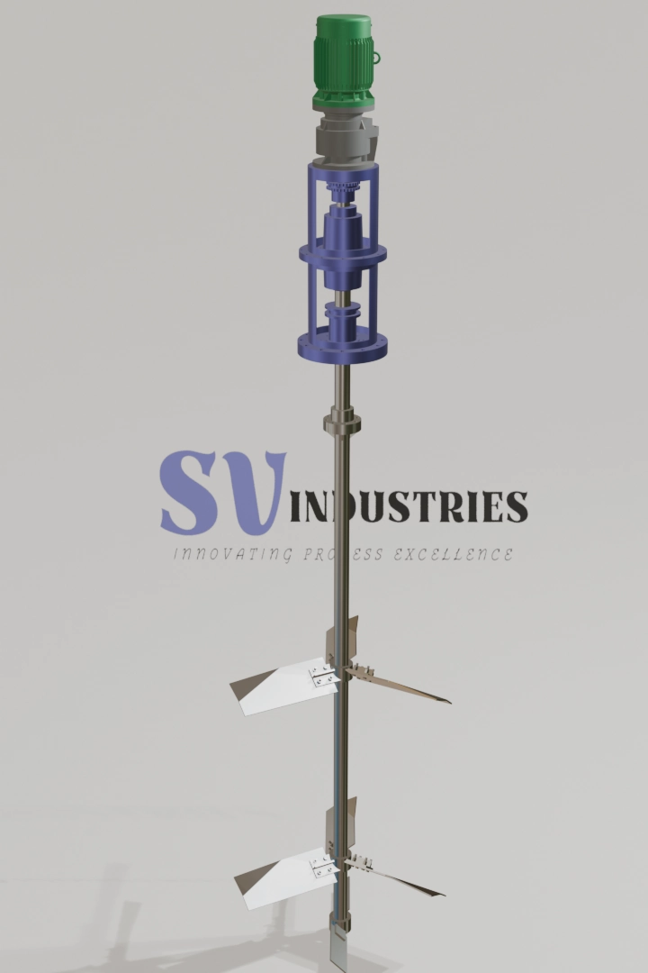
- Multi-stage or combination shafts pair hydrofoil low-shear stages with turbine high-shear stages for complex chemistries.
Include VFD control for ramping speed and refine torque estimation during specification. For critical or scale-up projects, confirm performance via pilot trial and CFD validation before finalizing the reactor agitator. SV Industries can propose staged impeller trains to balance shear and circulation for your process
Material selection & corrosion resistance
Selecting the right materials is a make-or-break decision when specifying an agitator for chemical process plants — compatibility affects corrosion resistance, product purity, and maintenance intervals. Match material selection to the chemical family, temperature, and abrasion risk to avoid premature failures and downtime.
Material choice starts with identifying process chemistry (acidic, alkaline, chlorides, solvents), SG, and operating temperature. For mildly corrosive, general-purpose duties, SS agitator options offer good longevity and cleanliness. For halides or strong acids, consider higher-alloy linings, clad components, or non-metallic coatings; for abrasive slurries choose wear-resistant faces or replaceable scrapers. Also evaluate weld-passivation, surface finish (Ra), and gasket/shaft-seal compatibility to prevent contamination and crevice corrosion.
| Chemical Family | Preferred Material Approach | Key Consideration |
|---|---|---|
| Neutral / mild corrosives | SS agitator (passivated) | Surface finish & maintenance |
| Chloride-bearing / acids | Clad alloys / lined components | Crevice corrosion & sealing |
| Abrasive slurries | Hard-facing / replaceable scrapers | Wear allowance & inspection |
| Solvents / organics | PTFE-lined or compatible seals | Swelling & solvent attack |
Include CFD validation for thermal or concentration-driven corrosion risks and plan for routine agitator maintenance (inspection ports, replaceable wear parts). SV Industries advises pilot trials for novel chemistries and can recommend a corrosion mitigation package tailored to your reactor.
Review our Agitator materials guidance and check compatibility with SS Jacketed Vessel options when specifying linings.
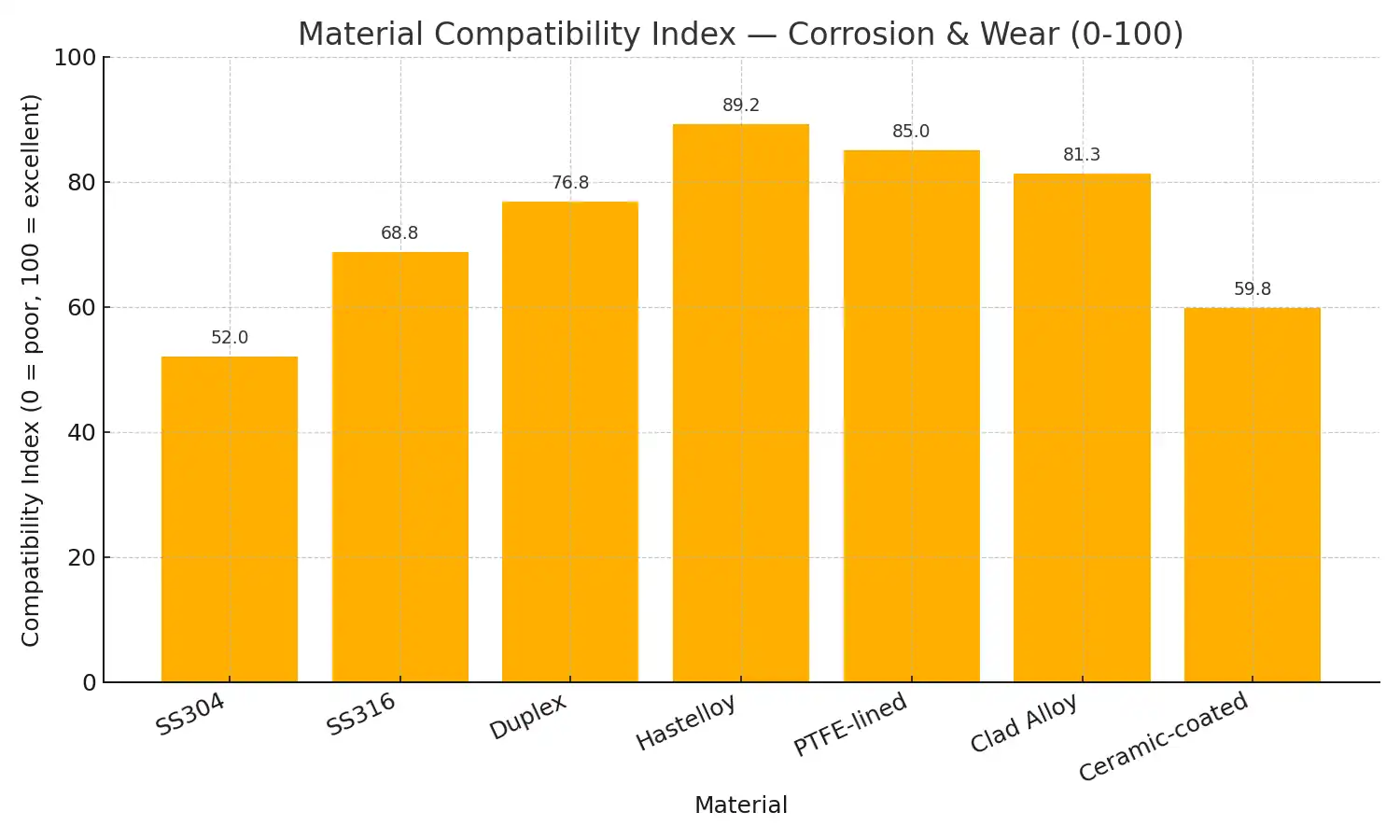
Material Compatibility Chart — Corrosion & Wear Index
Material mismatches are a common cause of early agitator failures and frequent maintenance; this chart summarizes practical compatibility indices to help choose a corrosion- and wear-resistant option. Assumption: indices normalized at 25 °C, weighted for chloride, strong acid, solvent and abrasive slurry exposure
Material interpretation:
Hastelloy and PTFE-lined options score highest (≈89 and 85), making them best for mixed chloride/acid/solvent duties, while SS304 is weakest (≈52) and risky in chloride-bearing acid services. Clad alloys and Duplex sit in the mid-high range — good compromise for many plants. Ceramic-coated parts excel for abrasive wear but have limited solvent/acid compatibility, so use where mechanical abrasion dominates. Engineering takeaway: select material to match the most aggressive expected service (chloride/acid if present), then optimize seals and maintenance intervals — contact SV Industries to convert this compatibility map into a material + linings spec for your reactor.
Sizing approach
Start sizing an agitator for chemical process plants by converting process goals into sizing inputs: tank volume, target mixing time, fluid viscosity class, and duty type (circulation, dispersion, suspension). The goal of agitator sizing is to specify a shaft and motor envelope that meets torque estimation and service duty without over-engineering the industrial agitator.
Follow a staged, conceptual approach: define worst-case fluid, pick candidate impeller types (axial vs radial vs scraping), estimate relative torque bands, then select a drive package with a VFD margin for transient conditions. Use CFD validation and a pilot trial where scale-up uncertainty is high — these steps reduce the risk of a mis-sized reactor agitator or costly agitator retrofit later.
| Step | Purpose | Deliverable |
|---|---|---|
| Define worst-case fluid | Fix design envelope | Viscosity class, SG |
| Choose impeller family | Match flow pattern | Impeller train concept |
| Estimate torque band | Drive selection | Shaft & motor envelope |
| Verify (CFD/pilot) | Confirm scale-up | Validated performance curve |
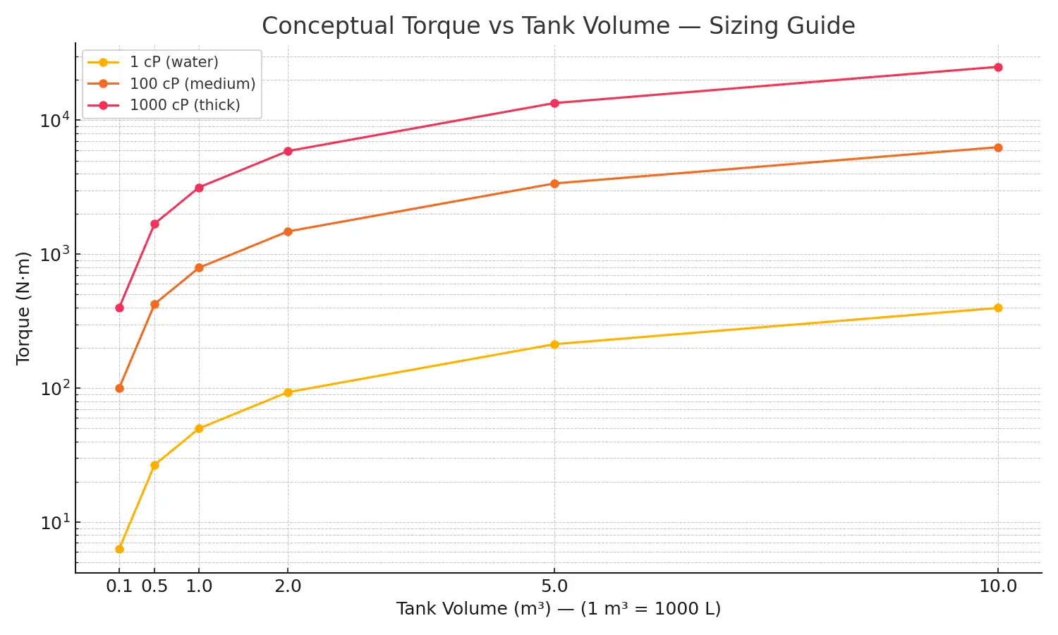
Sizing / Torque Calculation Chart — Conceptual Guide
Selecting an agitator requires estimating shaft torque across tank sizes and viscosities to size motors and gearboxes. This conceptual chart translates tank volume (m³) and viscosity (cP) into approximate torque (N·m) to highlight how viscosity dominates power needs. Assumption: normalized at D/T=0.33 and operating RPM ~150 (water-like SG=1.0).
Chart interpretation:
As the chart shows, torque rises strongly with viscosity and roughly with vessel size (near-linear exponent 0.9). Water-like fluids (1 cP) require modest torque (tens to a few hundred N·m), while 100–1000 cP fluids push torque into the thousands—doubling or tripling motor kW requirements. Engineering takeaway: design for the most demanding (highest cP) case, allow a VFD-start margin, and validate with a pilot test to avoid undersized shafts or gearbox overloads.
For conversion to a practical quote or gearbox spec, contact SV Industries or view our Reactor Vessel guidance.
Power, drives & control
Selecting the power, drives & control package is central when specifying an agitator for chemical process plants — it defines operational flexibility, torque estimation margin, and long-term reliability. Choose a drive strategy that matches duty cycles (continuous vs intermittent), variable loads, and maintenance access to avoid under-sized motors or frequent agitator maintenance.
Begin by defining the duty envelope (worst-case viscosity, start/stop duty, solids loading). For many industrial agitator applications a VFD is recommended to provide soft starts, speed range for multiple duties, and energy savings during low-load operation. Consider direct-drive vs gearbox vs belt/variation based on available shaft torque envelope and maintenance philosophy; magnetic couplings are an option for leak-sensitive services.
| Drive | Strength | Consideration |
|---|---|---|
| Direct drive | High reliability, low maintenance | Requires robust motor sizing |
| Gearbox | Compact for high torque | Service & alignment required |
| Belt/servo | Cost-effective, flexible | Higher maintenance, slippage risk |
Plan instrumentation (torque sensor, speed feedback), a protective motor starter, and interlocks. For critical scale-up, include CFD validation and a pilot trial to capture transient torque and confirm reactor agitator control strategies. SV Industries integrates VFDs and control logic into agitator packages to minimize retrofit headaches.
Learn more about our Agitator packages and related impeller options like the Pitch Blade Turbine when choosing drives.
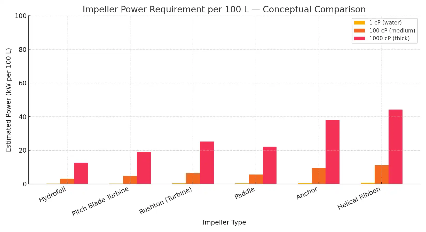
Energy & Power Comparison: Impeller Type vs Power Consumption
Low-level design choices (impeller family, expected viscosity (cP) and tank volume) drive operating power (kW) and lifecycle cost — this chart compares common impeller types across three viscosity classes to show relative kW demand. Assumption: normalized at D/T = 0.33, same tank geometry and tip-speed; values shown per 100 L (0.1 m³) and power scales with viscosity^0.6.
Interpretation & engineering takeaway
At 1 cP (water-like) the hydrofoil is the most energy-efficient (very low kW per 100 L). As viscosity rises to 100–1000 cP, power requirements climb nonlinearly (power ∝ viscosity^0.6) — Rushton and Pitch-Blade need moderate kW for dispersion, while Anchor/Helical demand the highest torque/power for viscous wall-sweep duties. Practical next steps: design equipment and select motors for the worst-case (highest cP), include VFD soft-start margin, and run a pilot trial for final sizing. For component selection and quotes, see our Agitator page or contact SV Industries.
Installation, commissioning & on-site validation
Proper installation, commissioning & on-site validation turn a specified agitator for chemical process plants into reliable plant performance — don’t treat this as an afterthought. Correct alignment, sealing, instrumentation set-up, and a staged commissioning plan prevent early failures, reduce vibration, and confirm that the industrial agitator meets mixing objectives under real process conditions.
Begin with mechanical checks: shaft alignment, coupling guards, bearing preload, and seal installation. Confirm electrical wiring, motor protection and VFD configuration for soft-start and ramp profiles. During wet commissioning, run at incremental speeds to capture torque and temperature trends; log speed, motor current, torque sensor output and key process variables. Use these records for baseline agitator maintenance planning and to set alarm thresholds.
Validation steps should include a short pilot trial or tracer test where feasible and a targeted CFD validation for complex internals. Verify homogeneity, suspension levels, gas dispersion (if applicable) and heat-transfer performance against process goals. If deviations appear, evaluate impeller position, baffle effectiveness, or consider an agitator retrofit rather than full replacement.
- Provide clear access for inspections and spare-part swaps.
- Tag wiring and document VFD parameters for future troubleshooting.
- Archive commissioning logs for warranty and performance claims.
Maintenance & troubleshooting
Selecting and running an agitator for chemical process plants is only half the job — disciplined agitator maintenance and a clear troubleshooting protocol keep your industrial agitator reliable, reduce downtime, and protect product quality. Early detection of bearing wear, seal leakage, imbalance, or control faults prevents costly agitator retrofit and unplanned shutdowns.
Start with a simple preventive checklist run weekly/monthly/quarterly based on duty:
- Daily visual: check seals, coupling guards, vibration alarms, and local instrumentation.
- Weekly mechanical: inspect shaft runout, coupling alignment, and fasteners; verify V-belt tension or coupling condition.
- Monthly electrical: log motor current, check VFD fault history, and confirm starter/interlock operation.
- Quarterly performance: compare mixing time, suspension levels and torque trends against baseline; run a tracer or simple test if homogeneity drops.
- Annual: full strip-and-inspect for wear parts, sacrificial blades, and seal faces; schedule replacement spares.
Include root-cause steps for common faults: rising motor current → check viscosity change/blocked impeller; vibration → verify balance, shaft alignment, or bearing wear; seals leaking → check gland, flush plan, and material compatibility.
For maintenance procedures tied to design, review our Agitator documentation and consult an Agitator Manufacturer – Gujarat for spare-part packages. SV Industries provides maintenance support and on-site troubleshooting to restore performance quickly.
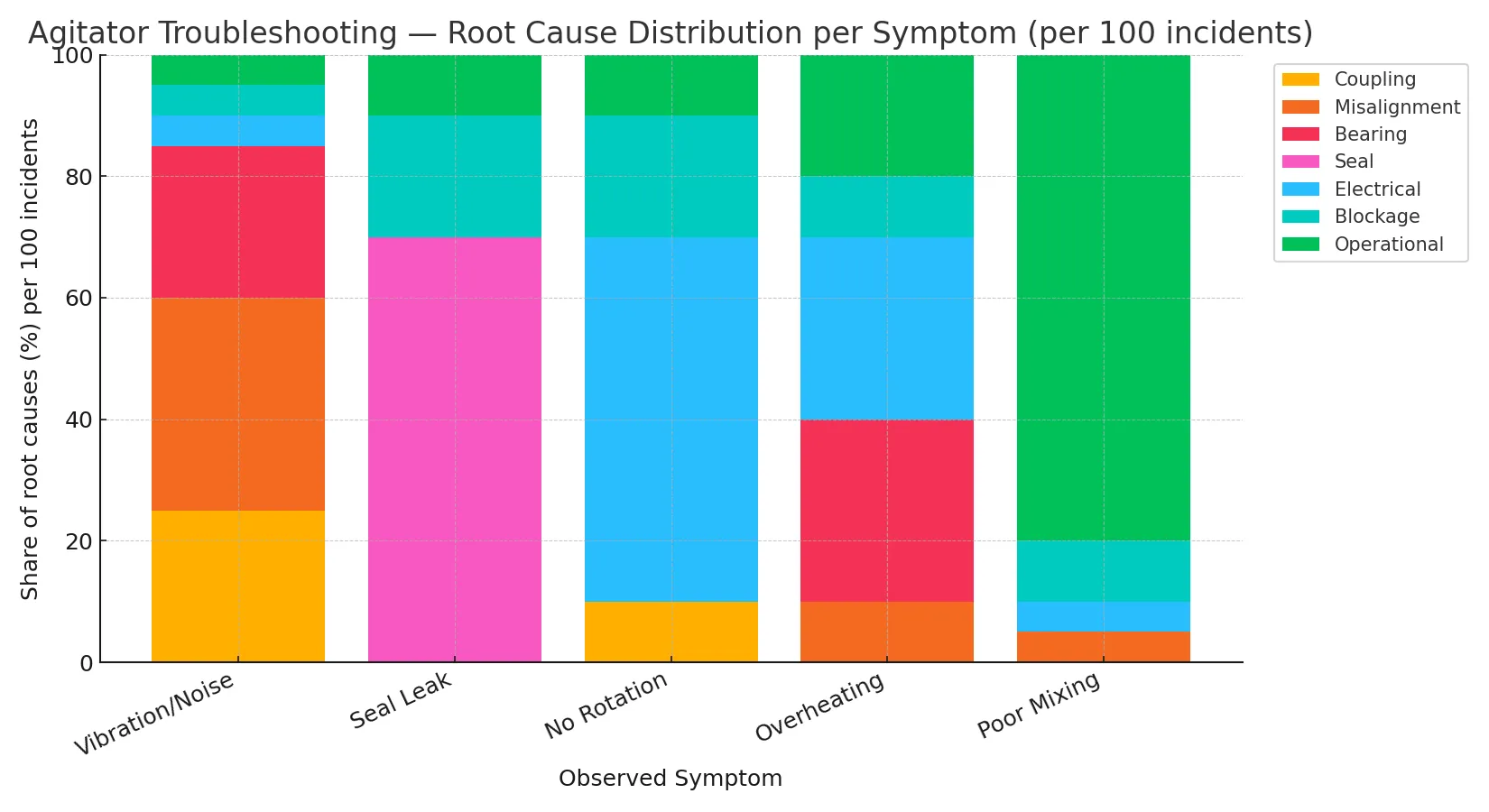
Agitator Troubleshooting — Root-Cause Distribution per Symptom
Many maintenance searches begin with a symptom (vibration, seal leak, no rotation) but operators need a quick, evidence-led path to likely root causes. This chart converts field heuristics into a root-cause share (%) per 100 incidents so teams can prioritise checks and spare parts. Assumption: illustrative, field-heuristic data normalized per 100 incidents for mid-size agitators (0.1–1 m³).
Interpretation & engineering takeaway
The stacked bars show which root causes dominate each symptom: seal failures overwhelmingly drive seal-leak incidents (~70%), while misalignment + coupling + bearing dominate vibration events. No rotation is mainly electrical (starters, supply) and blockages; poor mixing is mostly operational (wrong impeller, speed, baffles). Engineering takeaway: create symptom-based checklists (e.g., coupling → alignment → bearings for vibration) and pre-stock high-impact spares (seals, bearings, starters). Use this distribution to prioritise diagnostic steps in your on-site flowchart and reduce mean time-to-repair. For tailored troubleshooting and spare packages, see our Agitator guidance or contact SV Industries.
FAQs – Agitator for Chemical Process Plants
Which type of agitator for chemical process plants is best for my application?
Start by defining your goal — suspension, dispersion, heat transfer, or bulk blending. Typically, axial flow impellers like hydrofoil impellers are ideal for circulation and energy efficiency, while turbine impellers suit high-shear dispersion. The final choice depends on viscosity and tank geometry.
How do I know whether I need axial flow or radial flow?
As a rule: for fast bulk circulation with low shear → go for axial flow; for high-shear mixing, particle dispersion, or gas-liquid processes → select radial flow. Always validate with your worst-case viscosity condition.
What materials should be used for corrosive chemical mixing?
Identify your chemical family (acids, chlorides, solvents), temperature, and abrasiveness. For general service: use SS agitator (passivated); for harsh acids: use clad alloys or lined components; for solvents: PTFE-lined seals are ideal. Always check gasket and joint compatibility to prevent corrosion or leakage.
What information should I provide when requesting a quote?
Include essential data: tank volume, worst-case viscosity, specific gravity (SG), process goal (suspension/dispersion), available ports/manways, and expected duty cycle. This helps the agitator manufacturer give an accurate proposal with realistic torque estimation and VFD setup.
Can one agitator handle multiple duties like blending and dispersion?
Yes — but it usually requires a multi-stage impeller train or VFD-controlled operation. Always design for the most demanding shear/torque condition and validate using a pilot trial before finalizing.
How to reduce agitator power consumption?
Choose energy-efficient agitators like hydrofoil impellers, use a VFD to optimize speed, and ensure proper baffles and impeller-to-tank ratio. This minimizes unnecessary power draw while maintaining desired mixing performance.
What should I check before doing an agitator retrofit?
Inspect shaft alignment, mounting interface, available headroom, coupling type, and worst-case torque estimation. Often, a partial agitator retrofit — such as an impeller upgrade with a VFD — can improve performance without full replacement.
What tests are required during commissioning?
Perform stepwise speed checks, record motor current and torque, monitor vibration and seal performance, and validate homogeneity via tracer tests. These logs help set long-term maintenance schedules and alarm thresholds.
What are common troubleshooting signs that maintenance is needed?
Watch for excessive vibration, increased motor current, seal leakage, or sudden changes in mixing time. These indicate possible imbalance, bearing wear, or changes in fluid viscosity.
Request a Pilot Trial & Quote — Fast Track Your Agitator Selection
Ready to move from specification to performance? A clear call to action closes the gap between theory and plant-ready equipment — especially for an agitator for chemical process plants where scale-up risks matter. Offer a structured path: request a quote for a defined scope, or book a pilot trial when the duty is novel or viscous. Both options should include deliverables (validation plan, timeline, and deliverables such as CFD validation summary or pilot test report).
When requesting a pilot or quote, provide: tank volume (L/m³), worst-case viscosity (cP), SG, target mixing time, process goal (dispersion, suspension, heat transfer), and available ports. This lets an agitator manufacturer produce a meaningful proposal with torque estimation, VFD strategy, and spare-part recommendations rather than a ballpark price.
Make the conversion simple: offer a short intake form, an optional on-site survey, and a fixed-price pilot option. For complex duties, suggest a combined package — pilot trial + performance guarantee — so procurement and process teams convert faster with measurable risk reduction. SV Industries can run pilot trials, provide validated reactor agitator concepts, and convert results into a firm quote.
