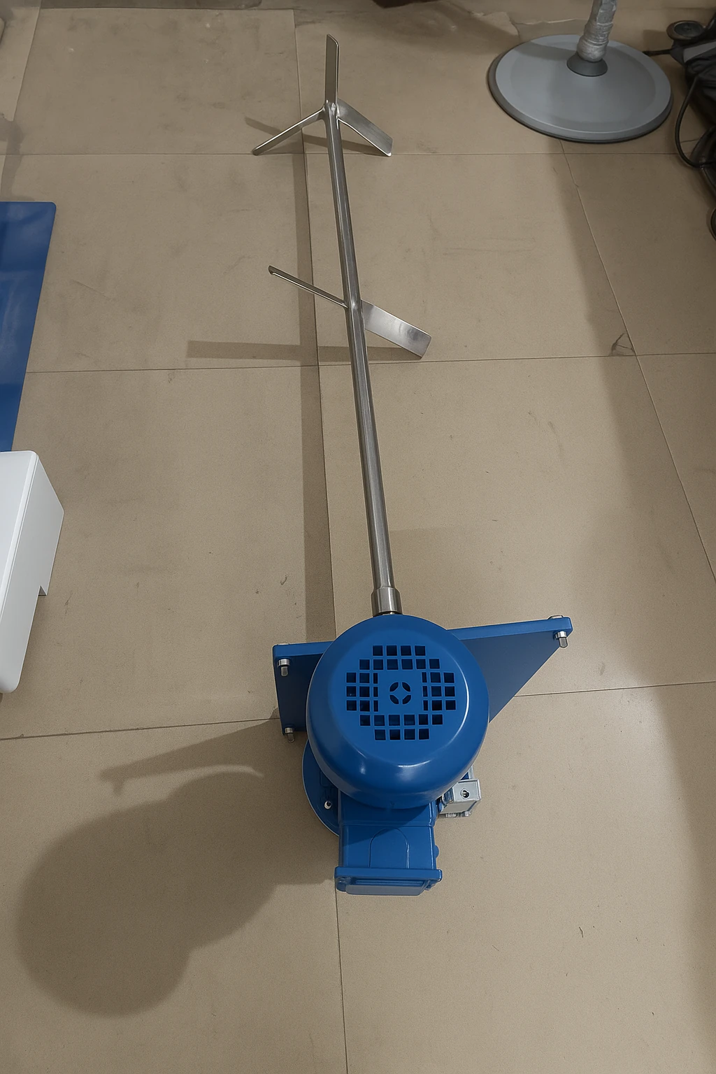
Industrial Stirrer Manufacturer
SV Industries designs and manufactures industrial stirrers engineered for reliable mixing across viscosities—from low-shear flow to high-torque, wall-sweeping duty. We size each system by viscosity (cP), SG, tank geometry, RPM, and power (kW) to deliver predictable results and long service life.
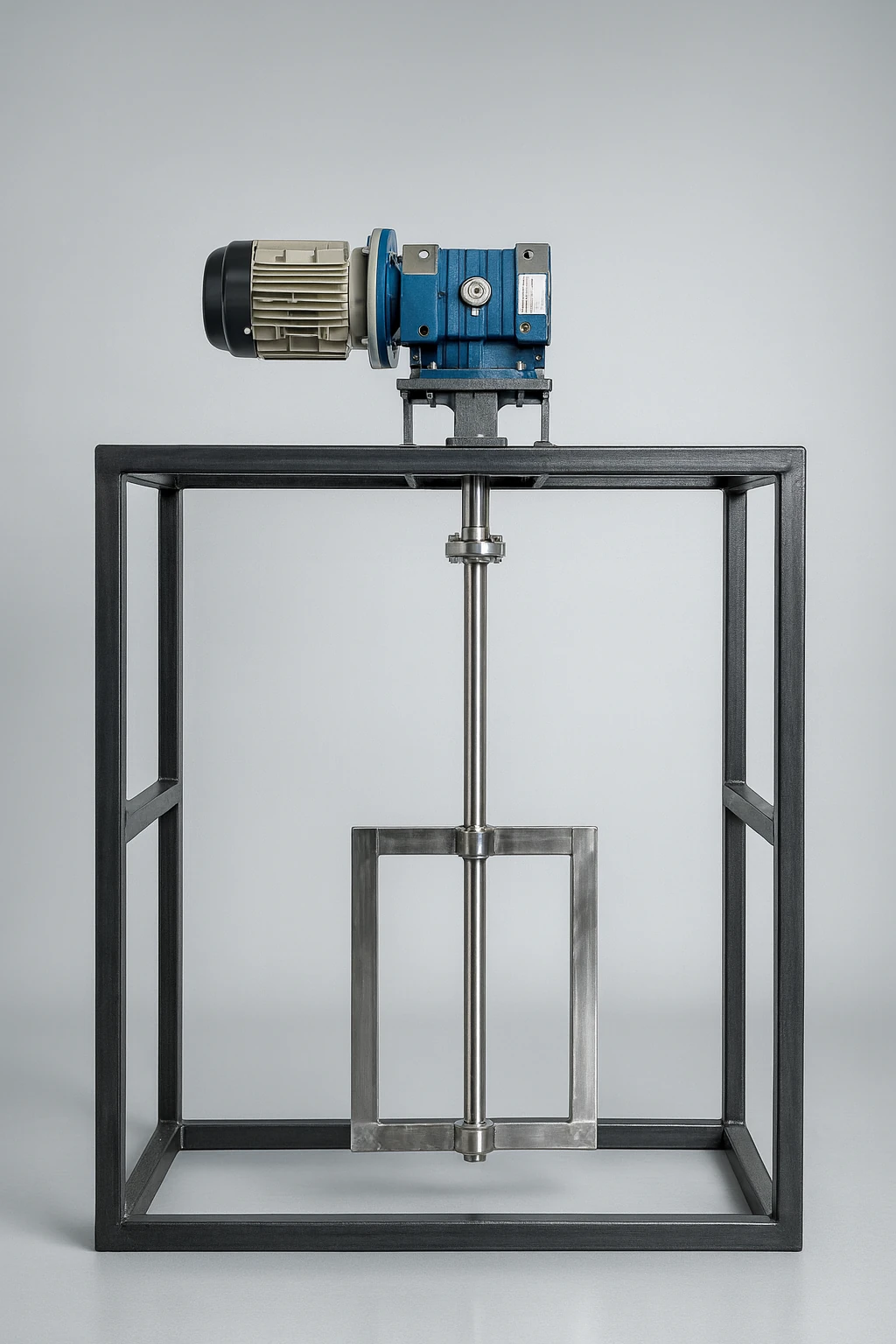
When plants ask for a “stirrer,” they usually need an agitator package: motor + gear unit, precision-balanced shaft, the right impeller (hydrofoil, pitch blade turbine, Rushton, anchor, paddle, helical ribbon), and mounting hardware with optional baffles, VFD, and mechanical seals. At SV Industries, we match the impeller to your process goal—bulk flow, suspension, blending, heat transfer, gas dispersion, or gentle floc preservation—then optimize D/T ratio, RPM, and kW to control shear and mixing time. Materials typically include SS304/SS316L with GMP-friendly finishes and traceable documentation.
If you’re comparing designs, start with the application fit. For flow-dominant, energy-efficient circulation, see our Hydrofoil Impeller. For broad, general-purpose duties, explore the PBT family next. Need an overview of complete systems? Review our Agitator page for assemblies, options, and QA checkpoints.
Selection note : Share fluid viscosity (min/typ/max), SG, tank ID × H, baffles (Y/N), target mixing time, and temperature. It speeds up accurate RPM & kW recommendations.
What Is an Industrial Stirrer? (Definition & Working Principles)
An industrial stirrer is a motor-driven mixing system (motor/gearbox, shaft, impeller) that creates controlled fluid motion to meet a process goal—e.g., blending, suspension, heat transfer, or gas dispersion. It’s a purpose-engineered agitator package sized by viscosity (cP), SG, tank geometry, RPM, and kW.
Clear definition: In plants, “stirrer” typically refers to a top-entry agitator: a drive + precision shaft + impeller (hydrofoil, pitch blade turbine, Rushton, anchor, paddle, helical ribbon). By setting D/T ratio, blade pitch, and RPM, we tune shear and flow to hit targets like mixing time or temperature uniformity. Materials are usually SS304/SS316L with GMP-friendly finishes.
How it differs from mixers/agitators:
- Stirrer vs Mixer (generic): “Mixer” is an umbrella term for many technologies (static mixers, inline high-shear, ribbon blenders). A stirrer is a rotary, tank-mounted solution.
- Stirrer vs Agitator: In process industries, the words overlap. Practically, “stirrer” = agitator assembly optimized for a given duty (low-shear flow, high-shear dispersion, wall-sweeping, etc.).
- When to choose:
- Low power, high circulation → hydrofoil.
- General purpose across viscosities → PBT.
- Gas dispersion/high shear → Rushton.
- High-viscosity/heat transfer → anchor/helical.
For a quick systems overview, see our Agitator page.

Mixing & Agitation Q&A
- Is a stirrer only top-entry? — Mostly yes; side-entry exists for large tanks.
- Do all stirrers create high shear? — No; impeller type + RPM set shear level.
- Which impeller is most energy-efficient? — Often hydrofoil for flow-dominant duties.
Stirrer Types & When to Use Each
Right impeller = right result. Match process goal (circulation, suspension, heat transfer, gas dispersion, gentle flocs) with viscosity band (cP), tank D/T, baffles, RPM & kW. Choose the design that meets target mixing time with the lowest practical power—often a hydrofoil for flow-dominant duties, or PBT for general purpose. See our detailed guides: Hydrofoil Impeller and Agitator.
Quick selection matrix
| Impeller | Best For | Viscosity (cP) | Typical RPM | Key Trait |
|---|---|---|---|---|
| Hydrofoil | Bulk circulation, heat uniformity, fragile solids | 1–1,000 | 120–300 | High pumping per kW (low shear) |
| Pitch Blade Turbine (PBT) | General-purpose blending & suspension | 1–5,000 | 80–250 | Balanced flow + shear |
| Rushton | Gas dispersion, emulsification | 1–200 | 150–600 | High shear; bubble breakup |
| Anchor / Gate | High-viscosity, wall-sweeping, heat transfer | 2,000–50,000+ | 20–80 | Scrapes boundary layer |
| Paddle | Gentle mixing, floc preservation, crystallization | 1–1,000 | 40–120 | Predictable velocities (low shear) |
| Helical Ribbon | Very high viscosity, paste-like masses | 20,000–200,000+ | 10–40 | Axial movement at low RPM |
Start with goal → viscosity band → tank D/T & baffles → D/T ratio → RPM (VFD). Unsure? Request a quick shortlist with RPM & kW sizing → Contact SV Industries.
Technical FAQs: Impellers, Shear & Sizing
- Energy-efficient option for thin liquids? — Hydrofoil (high pumping per kW).
- Best for gas–liquid dispersion? — Rushton or modified turbines at controlled RPM.
- >10–50 k cP slurries? — Anchor or helical ribbon with low RPM, high torque.
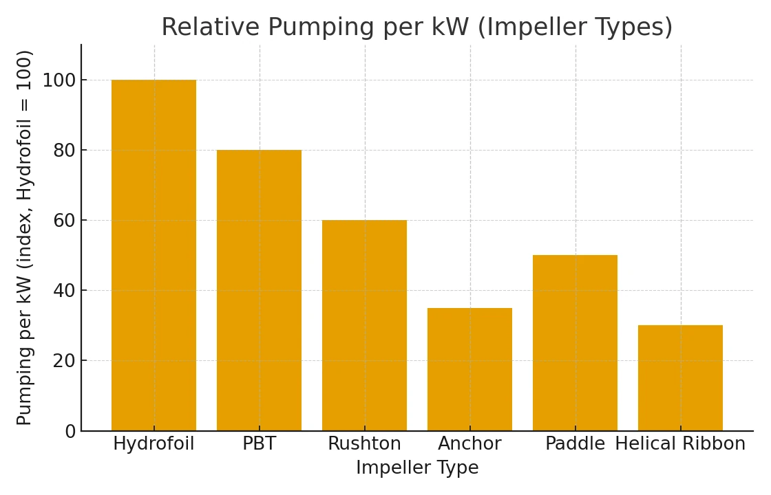
Relative Pumping per kW (Impeller Types)
Power bills drop when an impeller moves more liquid per kW. This comparison shows how different stirrer types convert motor power into bulk flow at similar diameters and RPM. Assumptions: normalized at D/T ≈ 0.33, water-like SG = 1.0, and comparable RPM bands.
Chart Explanation
Hydrofoils top the chart because their blade profile generates high axial flow with low shear, so you reach target mixing times at lower kW. PBT is a solid all-rounder where both flow and shear matter. Rushton prioritizes gas dispersion and shear, trading flow efficiency. Anchor and helical ribbon excel in high-viscosity duties at low RPM but naturally show lower pumping indices. For flow-dominant processes, shortlist a hydrofoil; for broad duties, start with a PBT. See the engineering notes on our Hydrofoil Impeller page.
Selection Guide: Viscosity, SG, Tank Geometry, Baffles & Shear Needs
Right stirrer = right physics. First map the fluid (viscosity in cP, SG), then the tank (ID × height, baffles, D/T), and finally your process goal (circulation, suspension, heat transfer, gas dispersion, floc care). This sequence ensures predictable RPM, kW and mixing time.
How to decide
| Input | Practical Range / Rule | Design Implication |
|---|---|---|
| Viscosity (cP) | 1–500: flow-dominant • 500–5k: mixed • >5k: high-visc. | Low cP → Hydrofoil/PBT; High cP → Anchor/Helical |
| SG (Specific Gravity) | 1.0–1.4 typical process range | Higher SG → more torque/kW margin |
| Tank Geometry | D/T (impeller/tank dia) ≈ 0.3–0.5 | Controls flow pattern & power draw |
| Baffles | 3–4 baffles, width ≈ 1/12 tank ID | Prevents vortex, boosts axial flow |
| Shear Need | Low shear (flocs) vs High shear (emulsify/gas) | Low → Hydrofoil/Paddle • High → Rushton/PBT |
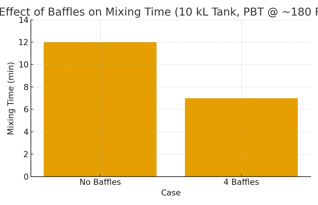
Effect of Baffles on Mixing Time
Baffles cut vortexing and push more axial flow, so the tank reaches uniformity faster at the same RPM and kW. Here we compare bulk mixing time for a top-entry PBT in a 10 kL tank. Assumptions: D/T≈0.33, water-like SG=1.0, ~180 RPM; adding 4 baffles reduces mixing time by ~40% in flow-dominant regimes.
Chart Explanation
With no baffles, swirling wastes energy and leaves dead zones, so the blend settles at ~12 min. Installing 3–4 baffles breaks swirl and deepens axial circulation, bringing time down to ~7 min. This improvement often lets you hold RPM/kW lower for the same spec, or keep power the same and get faster homogeneity. For high-viscosity cases, pair baffles with anchor/helical designs; for thin liquids, a hydrofoil or PBT with baffles is usually the most energy-efficient path. If you want sizing for your tank, share viscosity, SG and dimensions—start with our Agitator page and we’ll tune RPM & kW.
Design Features That Matter
A robust industrial stirrer is more than an impeller. Shaft stiffness, seal selection, bearing layout, drive/VFD sizing, and material/finish directly control reliability, hygiene, and kW draw. Get these right and you’ll hit mixing time with fewer stoppages and lower lifetime cost.
What to prioritize
| Feature | Why it matters | Practical spec |
|---|---|---|
| Shaft & couplings | Stability, vibration, critical speed margin | Stiffness ratio ≥1.3× duty; balanced to ISO G6.3 |
| Seals | Leak control, safety, hygiene | Mechanical seal (single/double) or stuffing box per media |
| Bearings & housing | Radial/axial load handling, shaft life | Service factor ≥1.5; proper lubrication & sealing |
| Drive & VFD | RPM control, soft-start, energy use | Right-angle/helical gearbox; VFD with torque boost |
| Materials & finish | Corrosion, GMP cleaning | SS304/SS316L; weld polish to Ra as required |
| QA & docs | Traceability, qualification | Balance, NDT (as needed), FAT, IQ/OQ packs |
Selection note
Impeller efficiency is wasted if the shaft/drive hit critical speeds or seals can’t handle pressure/chemistry. For flow-dominant duties pair the right drive with a hydrofoil; see our guide: Hydrofoil Impeller. For vessel-side heat transfer, match stirrer to the jacket design: SS Jacketed Vessel.
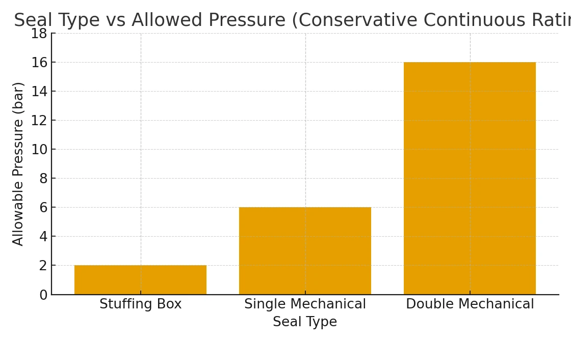
Seal Type vs Allowed Pressure
Seal choice sets your safe operating pressure and leakage risk. This comparison shows conservative, continuous-service pressure capability for common agitator seals at moderate speed. Assumptions: water-like SG=1.0, ~150 RPM, D/T≈0.33, ambient temperature; ratings represent practical operation, not burst.
Chart Explanation
A stuffing box is simple and low-cost, but practical operation is near 2 bar, with more leakage and maintenance. A single mechanical seal lifts capacity to ~6 bar with tighter emission control. A double mechanical seal (pressurized barrier) comfortably handles around 16 bar, suited for hazardous, volatile, or vacuum/pressure cycling duties. For pharma/solvent service, double seals also improve containment and CIP compatibility. If you’re unsure which seal fits your chemistry and pressure profile, share media, temperature, and duty cycle—we’ll pair the right seal with impeller selection. Start here: Contact SV Industries.
Sizing Snapshot (Typical RPM, D/T, and kW Ranges)
Quick sizing starts with tank volume (L/KL), impeller D/T, and the duty (flow-dominant vs high-viscosity). For thin to medium cP, hydrofoil/PBT at moderate D/T≈0.3–0.4 and 120–250 RPM is efficient; for thick media, anchor/helical use D/T≈0.45–0.55 and 20–80 RPM with higher torque.
| Parameter | Specification / Range |
|---|---|
| Mounting | Top-entry (flange/lantern); Side-entry on request |
| Impeller Options | Hydrofoil • PBT • Rushton • Anchor • Paddle • Helical Ribbon |
| Tank Size (Std.) | 0.5–30 kL (larger on request) |
| D/T Ratio | 0.30–0.55 (per duty) |
| Typical RPM | 10–300 RPM (VFD controlled) |
| Motor Power | 0.55–30 kW (higher on request) |
| Drives | Helical / Inline / Right-angle gearboxes; VFD with soft-start |
| Shaft | Solid SS, keyed/coupled; critical-speed margin maintained |
| Wetted Materials | SS304 / SS316L (others on request) |
| Surface Finish | Ra per URS; GMP polish & passivation available |
| Sealing | Stuffing box • Single mechanical • Double mechanical (pressurized) |
| Bearings | Heavy-duty housings; radial/axial load rated |
| Baffles (Tank) | 3–4 recommended (width ≈ 1/12 tank ID) |
| Temp / Pressure | As per media & tank rating; seal selection accordingly |
| Electrical | 415 V, 50 Hz (other voltages on request) |
| Protection | IP55/IP65 motors; flameproof/ex-proof on request |
| Instrumentation | VFD panel, RPM display, current/overload protection |
| Documentation | GA drawings, MTC/PMI, balance report, test certificates |
| QA / Testing | Dynamic balance ISO G6.3; FAT/run test with log |
| Compliance | GMP-friendly designs; SOPs/IQ/OQ packs when specified |
| Finish (Non-wetted) | Industrial enamel/PU per site standard; spares & service available |
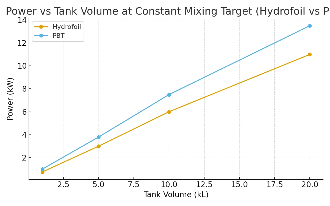
Power vs Tank Volume (Hydrofoil vs PBT at Constant Mixing Target)
As tanks scale from 1–20 kL, required motor kW rises non-linearly to maintain the same mixing time. Hydrofoils typically need less power than PBT thanks to higher pumping per kW. Assumptions: baffled cylindrical tank, D/T≈0.33, water-like SG=1.0, flow-dominant duty and similar RPM bands.
Chart Explanation
Both curves climb with volume, but the Hydrofoil line stays consistently below PBT—about 0.75 vs 1.0 kW at 1 kL, 6 vs 7.5 kW at 10 kL, and 11 vs 13.5 kW at 20 kL. That gap reflects the hydrofoil’s efficient axial flow profile, which reaches circulation targets at lower torque. For multipurpose tanks where some shear is desired, PBT remains a reliable choice—just budget a bit more kW or use a VFD to trim RPM. If you’re sizing a new system, share viscosity, SG and dimensions—we’ll recommend impeller type, RPM and motor kW starting points from our Hydrofoil Impeller and PBT design notes.
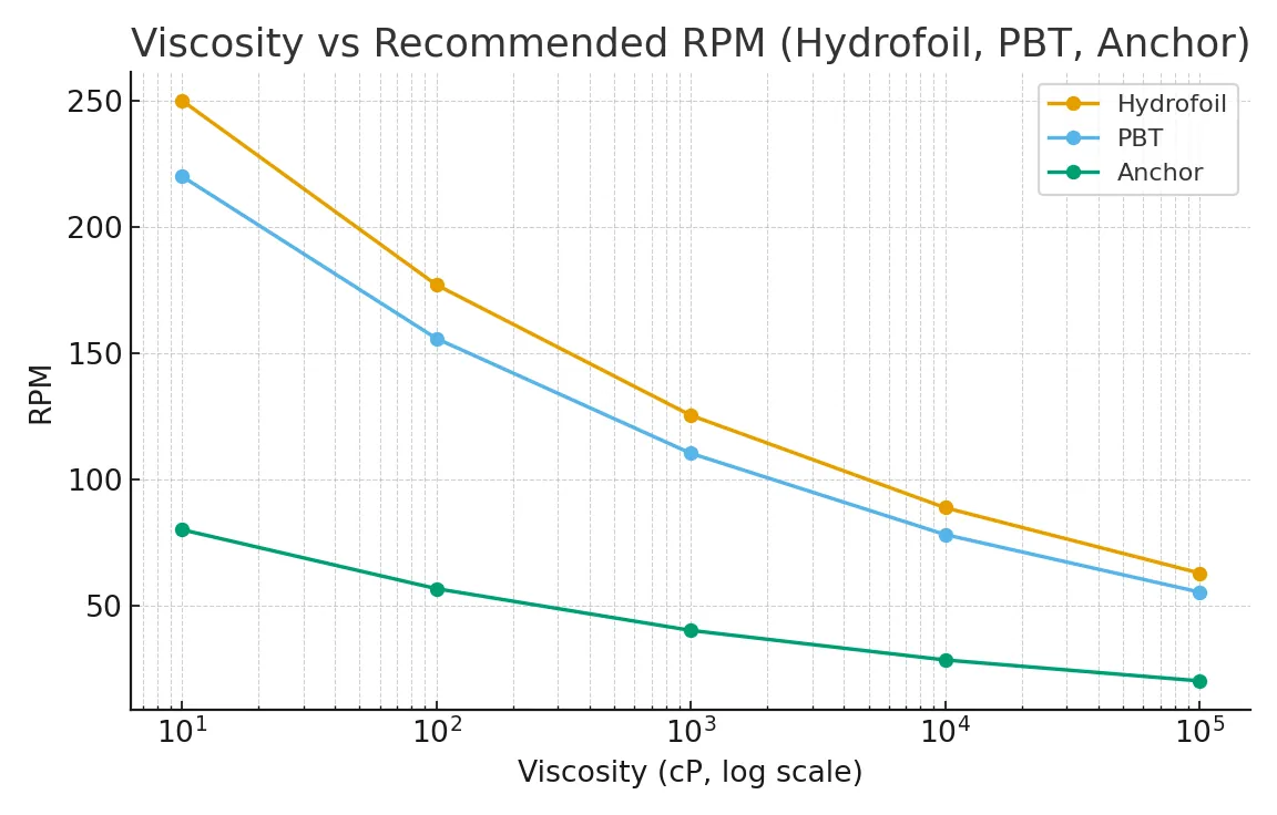
Viscosity vs Recommended RPM (Hydrofoil, PBT & Anchor)
As viscosity (cP) rises, safe operating RPM must drop to control shear and power draw while still achieving mixing time. This chart compares typical RPM bands for hydrofoil, PBT and anchor impellers across thin to high-viscosity duties. Assumptions: baffled cylindrical tank, D/T≈0.33, water-like SG=1.0, constant mixing objective.
Chart Explanation
All three curves decline with viscosity, but the anchor starts low and falls gently—ideal for 10–100 k cP media where wall-sweeping matters. Hydrofoil and PBT run faster in thin liquids (e.g., ~250/220 RPM at 10 cP) then taper to ~90/80 RPM near 10,000 cP. For fragile flocs or heat-sensitive batches, reduce RPM and favor larger D/T or anchors; for flow-dominant blending in low cP, hydrofoils minimize kW for the same mixing time. If you’d like duty-specific RPM and kW, share viscosity, SG and tank dimensions—start with our Hydrofoil Impeller guide.
Industries & Applications (Chemicals, Pharma, Food, Paints, ETP & More)
Each industry needs a different flow vs shear balance. Chemicals demand gas-dispersion or suspension control; pharma needs GMP finishes and cleanability; food favors gentle mixing; paints/inks need pigment de-agglomeration; ETP requires floc-safe low-shear. We size RPM, D/T, kW to your duty—then choose hydrofoil, PBT, Rushton, anchor, paddle or helical accordingly.
Typical duties at a glance
| Industry | Common Duty | Good First Choice |
|---|---|---|
| Chemicals | Neutralization, polymer mix, gas dispersion | PBT / Rushton (controlled shear) |
| Pharma & Biotech | Sanitary blending, heat transfer | Hydrofoil / Anchor, SS316L, GMP |
| Food & Beverages | Homogenization, syrup tanks | Hydrofoil / PBT (low-shear) |
| Paints & Inks | Pigment wet-out, viscosity shift | PBT / Anchor (torque + shear) |
| ETP/Water | Coagulation/flocculation, pH control | Paddle / Hydrofoil (gentle) |
Start with goal → viscosity band → tank D/T & baffles → D/T ratio → RPM (VFD). Unsure? Request a quick shortlist with RPM & kW sizing → Contact SV Industries.
Technical & Agitator Selection Q&A
- How to handle 20k cP? — Low RPM anchor/helical with higher torque.
- When do I add baffles? — Nearly always; they reduce vortex and kW waste.
- Which grade for pharma? — Prefer SS316L with documented Ra and passivation.
- Single vs double mechanical seal? — Double for hazardous/volatile media or higher pressure.
Compliance & QA (GMP, Surface Finish, Balance, NDT, FAT & Documentation)
Reliable mixing needs documented quality—from weld finish and material traceability to balance and seal testing. SV Industries delivers GMP-ready agitators with measured Ra, certified materials, calibrated instruments, and full FAT packs so your audits pass the first time.
What we certify & why it matters
| Checkpoint | Spec/Method | Outcome |
|---|---|---|
| Materials & MTC | SS304/SS316L with heat numbers + PMI | Traceability & corrosion assurance |
| Surface Finish | Measured **Ra** to URS; weld blend & passivation | Cleanability (GMP/CIP) |
| Dynamic Balance | ISO **G6.3** (or tighter where needed) | Low vibration; seal & bearing life |
| NDT (as applicable) | DPT/RT/UT on critical welds/shafts | Integrity under load/pressure |
| FAT & Run Test | No-load run, current draw, temperature, vibration | Verified performance before dispatch |
| Documents | DQ/IQ/OQ, GA drawings, SOPs, test reports | Audit-ready package |
Why SV Industries? (Engineering Depth, Customization, Service & Compliance)
We’re an industrial stirrer manufacturer that sizes agitators by duty → viscosity (cP) → tank geometry (D/T) → baffles → RPM & kW, then proves reliability with balancing, seal selection, and documented QA. Result: predictable mixing time at the lowest practical power—backed by GMP-ready paperwork.
What sets us apart
| Strength | What you get |
|---|---|
| Engineering-first sizing | Right impeller (Hydrofoil/PBT/Rushton/Anchor) with **RPM & kW** justified |
| Build quality | SS304/SS316L, ISO **G6.3** balance, sealed drives, VFD-ready packages |
| Compliance & docs | FAT reports, measured **Ra**, MTC/PMI, IQ/OQ packs (audit-ready) |
| Service | On-site assistance, spares, rapid troubleshooting |
Efficient impellers still fail without the right seal and shaft stiffness. We align design with your reactor/tank—see our About SV Industries and browse real builds in the Gallery.
Local Support Q&A
- Do you provide GMP-ready documentation? — Yes, with measured Ra, balance, and FAT packs.
- Can you help with RPM/kW optimization? — Absolutely—VFD tuning and duty-based sizing.
- What if my media is 20–50k cP? — Anchor/helical with low RPM and higher torque.
Frequently Asked Questions (FAQs) of Industrial Stirrer
How do I pick between a hydrofoil and PBT?
Hydrofoil = low-shear, high pumping per kW for 1–1,000 cP. PBT = balanced flow + shear for general duty up to ~5,000 cP.
How many baffles and how wide?
3–4 baffles, each ≈ 1/12 tank ID; full height with small wall gap. Reduces vortexing and mixing time.
Recommended RPM for 20–50k cP?
20–60 RPM using anchor/helical ribbon; size gearbox for torque and use VFD soft-start.
When is a Rushton turbine preferred?
Gas dispersion/emulsification where bubble breakup and high shear are critical—usually thin liquids (≤200 cP).
Top-entry vs side-entry—what’s the rule of thumb?
Top-entry for batch & versatility; side-entry for large storage/BT tanks where continuous low power circulation is needed.
What seal should I choose?
Low pressure/non-hazard: stuffing box or single mechanical. Hazardous/volatile or cycling pressure: double mechanical (barrier).
Do anchors help heat transfer?
Yes—wall-sweeping reduces boundary layer, improving jacket or limpet heat exchange in viscous media.
How to prevent pigment settling in paints?
Use PBT with proper baffles; tune RPM to achieve suspension height without over-shear.
What causes vibration after installation?
Misalignment, incorrect impeller level, inadequate baffles, or resonance near critical speed—check balance and mounting.
Do you help with reactors too?
Yes—stirrers are matched to vessel type and heat-exchange design; see our Hydrofoil Impeller notes and reactor pages, or Contact SV Industries for a duty-based shortlist.
Get a Quick Recommendation
Share a few process details and we’ll return a shortlist with impeller type, RPM, and motor kW—optimized for your mixing goal and energy use. Most quotes finalize in one iteration when inputs are complete.
What to send
Fluid: name, viscosity (min/typ/max in cP), SG, temperature range (°C).
Tank: internal ID × height (mm), liquid level (min/max), baffles (Y/N) and width, top/side entry.
Target: mixing goal (circulation/suspension/emulsion/heat transfer), mixing time (min).
Impeller constraints: material (SS304/SS316L), sanitary/GMP finish (Ra), mechanical seal preference, nozzle/clearance limits.
Utilities: available kW, RPM/VFD, drive preference (helical/inline/right-angle).
Scale: batch size (L / kL / m³), number of tanks, timeline.
Nice-to-have: sample photos/GA or quick sketch (no CAD needed).
What you’ll receive:
1–2 recommended impeller options (hydrofoil/PBT/Rushton/anchor/helical) with D/T, RPM, estimated kW, and notes on shear/heat transfer—plus upgrade options if required.
Send the above checklist and get a tailored recommendation → Contact SV Industries. For vessel math, try the Vessel Volume Calculator.
