
Concave Disc Impeller Manufacturer in India
SV Industries manufactures Concave Disc Impellers for industrial agitators and stirred vessels used in chemical, pharmaceutical and other process applications. Each impeller can be configured to suit the vessel, process fluid and required mixing duty.
The distinctive concave-blade design is commonly used where effective fluid dispersion and gas-liquid contacting are required. SV Industries can supply Concave Disc Impellers as part of a complete agitator system, with the impeller size, shaft arrangement and number of stages selected for the application.
What Is a Concave Disc Impeller?
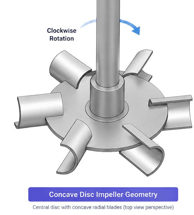
A Concave Disc Impeller is a disc-turbine impeller with concave radial blades arranged around a central disc and hub assembly. As the impeller rotates, the blade geometry produces predominantly radial discharge and creates the fluid motion needed for mixing and dispersion within the vessel.
The concave-blade configuration is particularly relevant to gas-liquid mixing and gas-dispersion applications, where effective operation depends on the balance between fluid circulation, turbulence, shear and gas handling. The same general impeller family may also be described as a Concave-Blade Disc Impeller or Concave-Blade Turbine.
Key Geometry & Configuration
- Central Disc & Hub — supports the blade assembly and connects it to the agitator shaft.
- Concave Radial Blades — the characteristic blade geometry of this impeller family.
- Disc-Turbine Configuration — primarily produces radial discharge around the impeller plane.
- Single or Multiple Stages — selected according to vessel geometry and process requirements.
Concave Disc Impeller, Concave-Blade Turbine & CD-6
Concave-disc designs are described by several related terms depending on the impeller geometry and application. Concave Disc Impeller remains the primary product name used by SV Industries.
Concave Disc Impeller
Concave Disc Impeller refers to the disc-turbine configuration with concave radial blades arranged around a central disc and hub for stirred-vessel mixing applications.
Concave-Blade Disc Impeller / Concave-Blade Turbine
Concave-Blade Disc Impeller and Concave-Blade Turbine are alternative terms used for the same general concave-blade disc-turbine family. The concave blade geometry distinguishes it from conventional flat-blade disc turbines such as the Rushton Turbine.
CD-6 / CD6
CD-6 is a specific designation associated with a concave-disc impeller developed for gas-dispersion service. It belongs to the same broader concave-blade disc-turbine category, but CD-6 is not a universal generic name for every Concave Disc Impeller.
Concave Disc Impeller Geometry & Construction
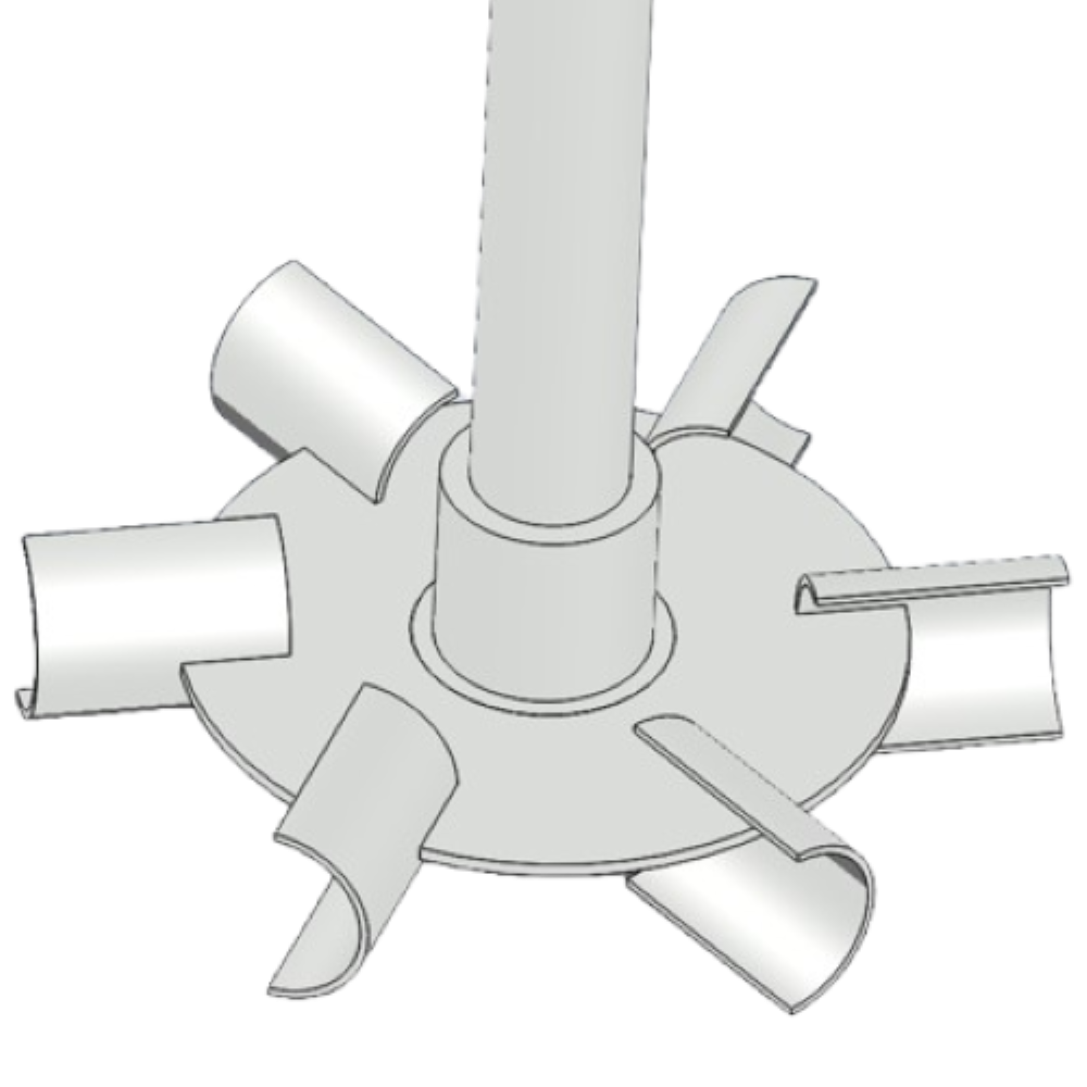
A Concave Disc Impeller combines a central disc, hub and concave radial blades into a compact disc-turbine assembly. The concave blade profile is the defining feature of this design and helps produce the radial discharge and gas-handling characteristics expected from this impeller family.
The final geometry is selected around the vessel size, process duty, fluid properties, gas flow requirement and agitator arrangement. Blade size, impeller diameter, hub design and shaft connection are selected for the specific application rather than from one fixed universal geometry.
Blade Arrangement
Concave Disc Impellers commonly use multiple concave blades positioned around the central disc. The blade curvature and orientation influence how fluid and gas are discharged from the impeller zone.
Disc & Hub Assembly
The central disc supports the blade arrangement and transfers torque from the shaft through the hub into the impeller. Hub and shaft connection details are selected to suit the agitator design and maintenance requirements.
Construction Options
Depending on the application and fabrication approach, concave-disc assemblies may use welded, bolted or adjustable construction. The final construction method should be selected around mechanical loading, maintenance access and process requirements.
Single or Multiple Impeller Stages
A Concave Disc Impeller may be used as a single stage or as part of a multi-stage agitator. Stage count and spacing depend on vessel geometry, liquid height and the required mixing or gas-dispersion duty.
How a Concave Disc Impeller Works
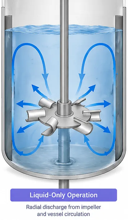
As a Concave Disc Impeller rotates, its blades move liquid outward from the impeller region, creating a predominantly radial discharge pattern. This discharge transfers momentum into the surrounding liquid and develops circulation within the vessel.
The concave blade shape also creates local turbulence and shear around the impeller. In gas-liquid service, these effects help disperse gas entering the impeller zone while the surrounding circulation distributes the dispersed phase through the vessel. The actual flow pattern depends on factors such as impeller diameter, speed, position, vessel geometry, liquid properties and gas flow rate.
Radial Discharge
Fluid leaves the impeller region mainly in the radial direction, producing strong motion around the impeller plane and contributing to vessel circulation.
Turbulence & Shear
Velocity differences around the concave blades generate turbulence and local shear. These effects are important for dispersion, phase interaction and mixing intensity.
Vessel Circulation
Radial discharge alone is only part of the mixing process. Vessel geometry, baffles, impeller position and additional stages influence how effectively the discharged fluid circulates through the complete liquid volume.
Gas Dispersion with a Concave Disc Impeller
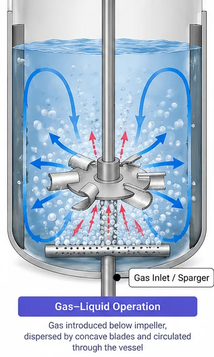
In gas–liquid applications, gas is typically introduced below the impeller through a sparger. As the Concave Disc Impeller rotates, the incoming gas is brought into the high-motion region around the blades, where it is dispersed into the surrounding liquid.
The concave-blade geometry combines gas dispersion, local turbulence and liquid circulation. These actions help distribute the gas through the vessel and increase contact between the gas and liquid phases. Actual performance depends on the gas flow rate, impeller speed and diameter, liquid properties, vessel geometry and impeller position.
Gas Entry & Bubble Dispersion
Gas introduced beneath the impeller enters the active mixing zone, where the rotating blades disperse and redistribute the gas into the surrounding liquid.
Gas–Liquid Contact
Dispersion creates gas–liquid interfacial area while turbulence around the impeller supports phase contact. This is important in processes where gas must be transferred or reacted with the liquid phase.
Circulation Through the Vessel
After leaving the impeller region, the dispersed gas is carried with the surrounding liquid circulation. Proper vessel circulation helps reduce localized gas accumulation and improves distribution through the working volume.
Avoiding Flooding
If gas flow becomes too high relative to the impeller’s operating conditions, effective radial dispersion can deteriorate and the impeller may approach a flooded condition. Gas rate, speed, impeller diameter and vessel geometry should therefore be evaluated together for gas-dispersion duty.
Concave Disc Impeller vs Rushton Turbine
Both the Concave Disc Impeller and Rushton Turbine are radial-flow disc turbines used in stirred vessels. The main difference is blade geometry: a Rushton Turbine uses flat vertical blades, while a Concave Disc Impeller uses concave blades arranged around the disc.
In gas–liquid service, this blade-shape difference affects cavity formation, gassed power behaviour and the amount of gas that can be dispersed before flooding becomes a concern. Under comparable gas-dispersion conditions, concave-blade turbines can provide more stable gas handling and are generally less sensitive to power unloading during gassing.
| Design Factor | Concave Disc Impeller | Rushton Turbine |
|---|---|---|
| Blade Geometry | Concave radial blades | Flat vertical blades |
| Impeller Family | Radial-flow disc turbine | Radial-flow disc turbine |
| Primary Flow Direction | Predominantly radial | Predominantly radial |
| Gas Dispersion | Well suited to gas–liquid contacting and gas-dispersion duties | Widely used for gas dispersion and strong local turbulence |
| Cavity Behaviour Under Gassing | Tends to develop smaller and later-forming gas cavities under comparable conditions | Larger gas cavities can develop as gas loading increases |
| Power Behaviour During Gassing | Generally less sensitive to gassing-related power reduction | Can show a larger reduction in power draw as gas loading increases |
| Flooding Behaviour | Can tolerate higher gas loading before flooding under comparable operating conditions | May reach flooding at lower gas loading for the same speed and diameter |
| Selection Basis | Gas rate, vessel geometry, liquid properties, impeller size, speed and process duty | Gas rate, shear requirement, vessel geometry, impeller size, speed and process duty |
Which One Should Be Selected?
A Concave Disc Impeller can be considered where gas handling, resistance to flooding and stable operation under gassed conditions are important design priorities.
A Rushton Turbine remains a well-established choice where strong radial flow, turbulence and local shear are required.
The final selection should not be based on impeller type alone. Gas rate, liquid properties, vessel dimensions, sparger arrangement, impeller diameter, speed and required process result should be evaluated together.
Applications of Concave Disc Impellers
Concave Disc Impellers are mainly considered for gas–liquid mixing and dispersion duties in stirred vessels. Their radial-flow, concave-blade configuration makes them particularly relevant where gas introduced into a liquid must be dispersed effectively while maintaining useful circulation through the vessel.
The final impeller choice depends on the required process result, gas rate, liquid properties, vessel geometry and operating conditions.
Gas Dispersion in Reactors
For stirred reactors where gas is introduced below the impeller and must be dispersed through the liquid phase.
Oxidation & Aeration
Applicable to processes where oxygen or another gas must be distributed through the liquid to support reaction or transfer.
Hydrogenation & Gas–Liquid Reactions
Can be considered for gas–liquid reaction systems where controlled gas dispersion and phase contact are important.
Fermentation & Bioprocess Mixing
Concave-disc configurations may be used as the lower gas-dispersion stage in multi-impeller systems, with upper impellers providing additional bulk circulation.
Absorption & Stripping
Relevant where gas–liquid contacting is required for transferring a component between the gas and liquid phases.
Multi-Impeller Gas–Liquid Systems
For taller vessels or duties requiring more than one stage, a concave-disc impeller can be combined with other impeller types to separate primary gas dispersion from bulk vessel circulation.
Typical process sectors:
• Chemical & Specialty Chemical
• Pharmaceutical & Fine Chemical
• Bioprocess & Fermentation
• Industrial Gas–Liquid Processing
How to Select a Concave Disc Impeller
A Concave Disc Impeller should be selected around the process objective and operating conditions, not from a fixed impeller diameter or speed range. For gas–liquid duties, the impeller, vessel and gas-introduction system work together, so each must be considered as part of the complete mixing system.
Key inputs include the required gas-dispersion duty, liquid properties, vessel geometry, gas rate, impeller position and available agitator power.
Process Objective
Define what the agitator must achieve—gas dispersion, gas–liquid reaction, aeration, mass-transfer support or another specific mixing duty.
Liquid Properties
Density, viscosity, rheology and operating temperature influence the required impeller size, speed and power.
Gas Flow & Operating Conditions
For gas-dispersion service, gas flow rate and operating pressure should be considered together with impeller speed and diameter to maintain effective dispersion and avoid flooding.
Vessel Geometry & Liquid Level
Vessel diameter, working liquid height, bottom geometry, baffles and operating level influence circulation and the number and position of impeller stages.
Impeller Diameter, Speed & Position
Impeller diameter, rotational speed and off-bottom position are selected together. There is no single universal diameter or RPM range suitable for every Concave Disc application.
Sparger & Multi-Stage Arrangement
Where gas is introduced through a sparger, its location relative to the lower impeller is important. Taller vessels may also require additional impeller stages for bulk circulation and gas distribution.
A Concave Disc Impeller should be evaluated as part of the complete agitator system. Changing impeller diameter, speed, stage count or gas rate can alter power demand, circulation and gas-dispersion behaviour, so these parameters should be reviewed together.
Concave Disc Impeller & Agitator Configuration
A Concave Disc Impeller is selected as part of the complete agitator system. The impeller, shaft, drive, number of stages and vessel geometry must work together to provide the required mixing and gas-dispersion performance.
For gas–liquid duties, the Concave Disc Impeller may be used as a single radial-flow stage or as the lower gas-dispersion stage in a multi-impeller arrangement, with upper stages selected to improve bulk circulation through the vessel. This lower-radial and upper-circulation arrangement can be used in gas–liquid systems, with the exact stage count and spacing selected for the vessel geometry and process duty.
Single-Stage Configuration
A single Concave Disc Impeller may be suitable where one radial-flow stage can provide the required mixing and dispersion within the working liquid volume.
Multi-Stage Configuration
Taller vessels or more demanding gas–liquid duties may require multiple impeller stages. Stage count, diameter, position and spacing should be selected from the vessel geometry and operating duty rather than from a fixed rule.
Combined Radial & Axial Stages
A lower Concave Disc Impeller can provide the primary gas-dispersion function while upper axial-flow or high-circulation impellers support top-to-bottom liquid movement. This separates the roles of gas dispersion and bulk circulation within the agitator system.
Shaft & Drive Selection
The shaft, gearbox and motor should be selected from the required impeller speed, power, operating torque, stage arrangement and mechanical loading. Adding or changing impeller stages can affect both process performance and shaft/drive loading, so the complete assembly should be reviewed together.
Concave Disc Impeller Materials & Fabrication Options
The material of a Concave Disc Impeller should be selected to suit the process fluid, corrosion conditions, operating temperature, cleaning requirements and mechanical duty. Material selection applies not only to the blades and disc, but also to the hub, shaft connection and associated wetted components.
SV Industries can configure the impeller construction around the application, with the final material grade, fabrication method and surface finish confirmed during engineering review.
When to Consider Another Impeller Type
A Concave Disc Impeller is particularly suited to selected radial-flow and gas-dispersion duties, but other impeller families may be more appropriate when the process is dominated by bulk circulation, solids suspension, mixed-flow blending or high-viscosity operation.
The correct choice should follow the process duty, fluid properties, vessel geometry and required flow pattern rather than the impeller name alone.
Rushton Turbine
Consider a Rushton Turbine where a conventional flat-blade radial disc turbine is preferred for strong local turbulence, shear and established radial-flow mixing duties. For higher gas-loading applications, concave-blade designs may offer advantages in gas handling, so the operating conditions should be compared before selection.
Hydrofoil Impeller
Consider a Hydrofoil Impeller when the main requirement is efficient axial pumping, strong bulk circulation or solids suspension in a low-to-moderate viscosity system. Hydrofoils generally create a stronger axial circulation loop than radial disc turbines.
Pitched Blade Turbine
A Pitched Blade Turbine (PBT) can be considered where a combination of axial and radial movement is useful for general blending, suspension or mixed-flow duties. Its discharge contains both axial and radial components rather than the predominantly radial flow of a Concave Disc Impeller.
Anchor Impeller
For high-viscosity or laminar-flow duties, a close-clearance Anchor Impeller may be more appropriate than a turbine-style Concave Disc Impeller. Anchor designs are particularly relevant where wall-region movement, viscous circulation or heat-transfer support is important.
Selection Note: No single impeller is optimal for every mixing duty. Gas handling, circulation, shear, viscosity, solids behaviour and vessel geometry should be evaluated together before final selection.
Concave Disc Impeller FAQs
What is a Concave Disc Impeller?
A Concave Disc Impeller is a radial-flow disc-turbine impeller with concave blades arranged around a central disc and hub. It is particularly relevant to stirred-vessel applications requiring gas dispersion, gas–liquid contacting and controlled radial mixing.
Is a Concave Disc Impeller the same as CD-6 or CD6?
CD-6 / CD6 is a specific designation associated with a well-known concave-disc gas-dispersion impeller design. It belongs to the broader concave-blade disc-turbine family, but the term CD-6 should not be used as a universal generic name for every Concave Disc Impeller.
What flow pattern does a Concave Disc Impeller produce?
A Concave Disc Impeller produces a predominantly radial discharge from the impeller region. The resulting flow interacts with the vessel, baffles and surrounding liquid to develop circulation through the working volume.
Why are Concave Disc Impellers used for gas–liquid mixing?
The concave blades create turbulence and radial discharge around the impeller, helping disperse gas introduced beneath the impeller into the surrounding liquid. Effective performance depends on gas flow rate, impeller speed and diameter, liquid properties, vessel geometry and sparger arrangement.
What is the difference between a Concave Disc Impeller and a Rushton Turbine?
Both are radial-flow disc turbines, but their blade geometry differs. A Rushton Turbine uses flat vertical blades, while a Concave Disc Impeller uses concave blades. In suitable gas-dispersion duties, concave-blade designs can provide more stable gas handling and reduced sensitivity to gassing-related power unloading compared with conventional flat-blade turbines.
Can a Concave Disc Impeller be used in a multi-stage agitator?
Yes. It may be used as a single stage or as the lower gas-dispersion stage in a multi-impeller system. Upper stages can be selected to provide additional bulk or top-to-bottom circulation where required.
What materials are available for Concave Disc Impellers?
Material selection depends on the process fluid, corrosion conditions, temperature and cleaning requirements. Typical construction may include carbon steel, stainless steel such as SS316 / SS316L, or special alloys where required for the service.
How are the impeller diameter and speed selected?
There is no single universal diameter or RPM suitable for every application. Impeller diameter and rotational speed should be selected together with vessel size, liquid level, fluid properties, gas rate, process objective, stage arrangement and available agitator power.
Related Agitator & Impeller Solutions
A Concave Disc Impeller is one part of the complete mixing system. Depending on the process duty, the application may require a complete industrial agitator, a reactor vessel, or another impeller geometry with a different flow and shear characteristic.
01
Industrial Agitator
Agitator systems configured for blending, suspension, heat transfer and other process mixing duties.
02
Reactor Vessel
Custom reactor vessel design and fabrication for project-specific mechanical and process requirements.
03
Rushton Turbine
A conventional flat-blade radial disc turbine used where strong local turbulence, shear and radial-flow mixing are required.
04
Hydrofoil Impeller
An axial-flow impeller suited to applications where efficient pumping, bulk circulation and solids suspension are important process requirements.
Discuss Your Concave Disc Impeller Requirement
If you are evaluating a Concave Disc Impeller for a new agitator, reactor mixing system or retrofit application, share the available process and vessel information with SV Industries.
Provide details such as process duty, vessel dimensions, working volume, liquid properties, viscosity, operating temperature and pressure, gas type and flow rate, sparger arrangement, material of construction and existing agitator details. These inputs help define the appropriate impeller diameter, speed, stage arrangement and overall agitator configuration for the application.