Limpet Coil Length Calculation – Dished End & Shell
limpet coil length is essential—especially across dished ends and cylindrical shells, where curvature, pitch, and forming method directly affect material consumption and project cost. This blog introduces an interactive calculator that estimates the Total Coil Length for 1 Dished End + Shell, speeds up procurement planning, and lets you download a PDF report with all inputs and results.
A limpet coil (half-pipe jacket) is welded to the vessel’s exterior to enable efficient heating or cooling in reactors and tanks. Unlike straight runs on flat surfaces, dished ends introduce bending stretch and geometry-driven nuances that make manual calculation slow and error-prone. The calculator streamlines this with field-validated logic, a unit toggle (mm/meters ↔ inch/feet), and a single total length highlight so you can move from design to cutting plans faster.
Important, practical note: The calculator provides a practically calculated estimate. Exact values may vary slightly (±2–5%) due to bending stretch, neutral-axis shift, pitch tolerance, weld overlap, spring-back, and on-site fit-up. For ordering and cutting, include a 2–5% allowance.
Limpet Coil Length Calculator – Dished End & Shell
Dished End – Results
Shell – Results
Overall (1 Dished End + Shell)
What is a Limpet Coil?
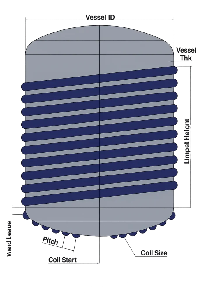
A limpet coil is a half-pipe jacket welded to the outer surface of a vessel to circulate heating or cooling media (steam, thermal oil, chilled water, brine). It enables efficient heat transfer without a full external jacket and is commonly applied on cylindrical shells and dished ends of reactors and tanks.
🔬 Definition:
A limpet coil is formed by welding semi-circular (half-pipe) sections in a helical or serpentine path on the vessel exterior. Media flows through this channel to add or remove heat from the process inside the vessel.
⚙️ Construction Basics:
- Placement: Wrapped over the shell and can be continued over dished ends.
- Flow pattern: Single-start or dual-start spiral; inlet and outlet nozzles placed for optimal drainage/venting.
- Sizes: Typical coil sizes are NB 25 / NB 40 / NB 50 (varies with duty and pressure).
- Materials (MOC): SS304, SS304L, SS316, SS316L, or MS, selected by corrosion resistance, temperature, and budget.
- Welding: Continuous or intermittent (stitch) based on design; full-penetration at butt joints of the half-pipe.
🌡️ Heating/Cooling Media:
Steam, thermic fluid (hot oil), hot water, chilled water, or glycol/brine for sub-ambient service. Media selection and allowable ΔT drive coil sizing, pitch, and coverage area.
📐 Key Parameters:
- Vessel
ID & shell height (defines wrap length and coverage).
- Coil
size & pitch (controls surface area and pressure drop).
- Coverage
strategy (shell only vs. shell + dished ends).
- Allowable
pressure & test pressure of the coil circuit.
- Thermal
duty (kW), target temperature program, and fouling factors.
🏭 Typical Applications:
Ideal for chemical and industrial reactors, storage tanks, and process vessels where targeted heating/cooling is needed without the complexity of a full jacket.
🔗 Explore related pages:
- Compare with a full jacket: SS Jacketed Vessel → https://sv-industries.com/ss-jacketed-vessel/
- Reactor integrations: Limpet Coil Reactor Vessel → https://sv-industries.com/limpet-coil-reactor-vessel/
How Coil Length is Calculated (Dished End + Shell)
The calculator finds coil length at the coil centerline. For the shell, each helical turn length is √[(π·D₍c₎)² + p²], multiplied by the number of turns. For the dished end, it uses a segmented-arc method (crown + knuckle rings) and sums √[(2π·rᵢ)² + p²] across rings. Total = Shell + One Dished End, shown in metric and imperial with an optional allowance.
🔬 Definition:
- D₍c₎ (Centerline Diameter): Effective diameter at the neutral axis of the half-pipe (vessel outside diameter plus the offset to the coil’s flow centerline).
- p (Pitch): Crest-to-crest spacing of the half-pipe wrap, measured perpendicular to the helix path.
- Centerline Length: All lengths are computed along the flow centerline of the half-pipe (best proxy for material needed).
🔄 Total, Units & Allowance
- Total (reported): L_total = L_dish (one end) + L_shell
- Units: Results show in meters & feet; input toggle supports mm/meters ↔ inch/feet.
- Allowance (optional):
- Order Length = L_total × (1 + Allowance%)
- Typical allowance: 2–5% for trim, weld overlap, spring-back, and pitch variation.
🧩 Practical Assumptions & Tolerances
- Centerline offset includes half-pipe geometry and weld build-up; local practice may vary.
- Pitch is treated as effective pitch (as laid).
- Weld overlap at joints is generally covered via allowance, not per-joint addition.
- Expected variation: ±2–5% in real fabrication due to bending stretch, neutral-axis shift, fit-up, and on-site adjustments.
✅ Engineering Checks (Before Finalizing)
- Coverage matches specification: shell only vs shell + dished end.
- Inlet/outlet location supports drainage/venting of the coil circuit.
- Minimum lead length available for nozzles and transitions.
- Pressure/temperature suitability if you are comparing with SS Jacketed Vessel alternatives.
- Process duty context (heating/cooling) per Chemical Process Reactor or Industrial Chemical Reactor selection.
- For vessel context and variants, see Reactor Vessel; for jacketed-coil projects, review Limpet Coil Reactor Vessel.
📎 Note for Readers
This calculator returns a practically calculated estimate. Exact values can differ slightly (±2–5%) in production; include allowance when creating cutting lists or placing material orders.
Why Use This Calculator?
⏱️ Save time on complex geometry
Manual calculation on dished ends + shells is slow and error-prone. The tool automates helical and segmented-arc math so you can move from design to cutting plans faster.
🧮 Field-aligned logic, less guesswork
Calculations are performed at the coil centerline with a ring-sum approach on dished ends—closer to real fabrication than flat-surface approximations.
🔧 Purpose-built for fabrication planning
See a single Total Coil Length (1 Dished End + Shell), optionally add Allowance (%), and derive an Order Length directly for procurement.
🔁 No manual conversions
Instant unit toggle (mm/meters ↔ inch/feet) reduces spreadsheet errors and keeps quotes consistent for domestic and export projects.
📑 Shareable documentation
Generate a downloadable PDF report that captures inputs and results for internal reviews, vendor discussions, and project records.
📈 Better costing & scheduling
Quickly compare lengths for different pitches, coil sizes (NB 25/40/50), and coverage strategies to refine material estimates, lead times, and budgets.
🛠️ Practical by design
Outputs are practically calculated estimates; exact values can vary slightly (±2–5%) due to bending stretch, neutral-axis shift, pitch tolerance, weld overlap, spring-back, and on-site fit-up. Include an appropriate allowance before ordering.
Practical Example (To Be Filled)
Input Values (Illustrative)
🏷️ Vessel ID: 2000 mm
📏 Shell height: 3000 mm
🔁 Pitch (crest-to-crest): 120 mm
🔩 Coil size (half-pipe): NB 80 (illustrative)
🧱 Assumed shell thickness (to estimate outside/centerline diameter): ≈ 12 mm (illustrative)
🎯 Coverage: 1 dished end + shell
Note: These are sample inputs to demonstrate the workflow. Use your actual project values for real calculations.
Output (Meters & Feet)
Dished end coil length: 15.986 m (≈ 52.448 ft)
Sum of helical turns over one dished end, computed at the coil centerline by adding ring-by-ring helix lengths from the knuckle toward the crown (circumference shrinks as radius decreases). With pitch = 120 mm, head height typically gives ~4 full turns + a partial.Shell coil length: 127.262 m (≈ 417.526 ft)
Helical wrap over the cylindrical shell at the coil centerline. For shell height = 3000 mm and pitch = 120 mm, turns N = 3000 / 120 = 25.
Formula used for one helical turn (plain text):L_turn = sqrt( (pi * Dc)^2 + p^2 )
Implied per-turn helix length from total:127.262 m / 25 = 5.09048 m/turn
Approximate effective centerline diameter (since pi*Dc ≈ 5.088 m): Dc ≈ 1.62 m. Helix vs circumference adds only ~0.045% per turn at this geometry.Total coil length (1 DE + Shell): 143.248 m (≈ 469.974 ft)
Simple sum:15.986 m + 127.262 m = 143.248 m
Share of total: Shell ≈ 88.84%, Dished end ≈ 11.16%.
What affects these numbers the most
Pitch (p): Smaller pitch → more turns → higher total length (both shell and dish).
Effective centerline diameter (Dc): Larger Dc (e.g., larger vessel or larger coil centerline offset) → longer per-turn length.
Coverage height: More shell height or deeper dish coverage → more turns → longer length.
Coil size (NB): Changes the centerline offset of the half-pipe; bigger NB generally increases Dc slightly and length per turn.
Practical note
These outputs are practically calculated estimates along the coil centerline. In fabrication, bending stretch, neutral-axis shift, pitch tolerance, weld overlap, spring-back, and on-site fit-up can introduce ±2–5% variation. For ordering/cutting, include an allowance (e.g., 2–5%) on top of the calculated total.
Frequently Asked Questions (FAQs)
How do I calculate limpet coil length on a dished end?
Select head type, enter Vessel ID, Pitch, Coil Size (NB/OD), start distance from dish center, and weld leave. The calculator integrates the spiral path to give total length and turns.
Which dished end types are supported
ASME F&D (torispherical), 2:1 Ellipsoidal, and Hemispherical heads.
Do I input ID or OD?
Use Vessel internal diameter (ID). Coil OD is auto-mapped from the selected NB size.
Can I switch units?
Yes. Toggle between meters/millimeters and inch/feet. Results update instantly.
How is weight calculated?
Weight = half-pipe steel cross-sectional area × calculated length × material density (SS 304/304L/316/316L/MS).
How accurate is the result?
It’s a practical estimate. Allow ±2–5% for bending stretch, pitch tolerance, weld overlap, and on-site fit-up. Add scrap and lead-in/out in procurement.
Can I export the result?
Yes, download a PDF summary or print directly from the page.
